Rosemount
™
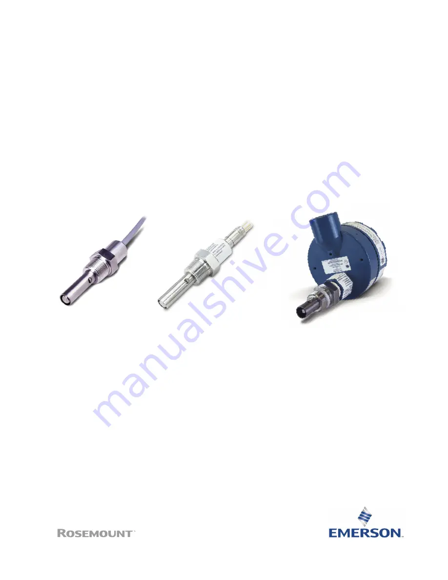
400 and 400VP
Contacting Conductivity Sensors
Instruction Manual
LIQ-MAN-400
Rev. L
May 2017
Страница 1: ...Rosemount 400 and 400VP Contacting Conductivity Sensors Instruction Manual LIQ MAN 400 Rev L May 2017 ...
Страница 2: ...hasgkas ...
Страница 3: ...d by Emerson Unauthorized parts and procedures can affect the product s performance place the safe operation of your process at risk and VOID YOUR WARRANTY Third party substitutions may result in fire electrical hazards or improper operation Ensure that all equipment doors are closed and protective covers are in place except when maintenance is being performed by qualified persons to prevent elect...
Страница 4: ...ovides concerning all revisions of this document Rev Level Date Notes J 10 2016 Updated information with new Emerson Style Guidelines Added Ordering Information Added Accessories Information Added dimensional drawings K 11 2016 Updated Ordering Information and Specification L 05 2017 Updated the Emerson Address and Logo About This Document ...
Страница 5: ...iring the sensor 5 2 2 Wiring the sensor to the transmitter 5 Section 3 Calibration and Maintenance 3 1 Calibrating the sensor 9 3 2 Cleaning the sensor 12 Section 4 Troubleshooting 4 1 Troubleshooting 13 Section 5 Accessories 5 1 Accessories 15 Instruction Manual Table of Contents LIQ MAN 400 May 2017 Table of Contents i ...
Страница 6: ...Table of Contents Instruction Manual May 2017 LIQ MAN 400 ii Table of Contents ...
Страница 7: ... Maximum pressure 250 psig 1825 kPa abs Vacuum At 1 6 in Hg air leakage is less than 0 005 SCFM 0 00014 m3 min Cell constants 0 01 0 1 and 1 0 cm Process connection in MNPT Cable 10 ft 3 1 m standard 50 ft 15 2m optional interconnecting VP6 cables sold separately see Accessories Table 1 2 Flow cell 24092 02 specifications Wetted materials Body and Nut Polycarbonate and polyester in Fittings 316 St...
Страница 8: ...ansmitter models 56 1056 1057 1066 5081 and legacy transmitter models 1055 54C 54eC 4081C 6081 C and XMT C 2 5 5 inches from the bottom of threads to tip of sensor Table 1 4 Rosemount 400VP Contacting Conductivity Sensor with Variopol cable connection ordering information Model Sensor type 400VP Contacting Conductivity Sensor Cell constant 11 0 01 cm 12 0 1 cm 13 1 0 cm Temperature compensation _ ...
Страница 9: ...low cell with the sample draining to open atmosphere bubbles may accumulate on the electrodes Trapped bubbles will cause errors As bubbles accumulate the conductivity reading normally drifts down In the plastic flow cell bubbles are readily visible To control bubble formation apply a small amount of back pressure to the flow cell or pipe tee Section 2 Installing the sensor Figure 2 1 Sensor orient...
Страница 10: ... 11 28 15 6 49 164 9 1 0 cm 0 667 16 94 1 13 28 70 6 51 165 4 0 01 cm with extended insertion length 1 59 40 39 5 49 139 4 10 90 276 9 0 1 cm with extended insertion length 0 687 17 45 5 49 139 4 10 90 276 9 1 0 cm with extended insertion length 0 667 16 94 5 49 139 4 10 90 276 9 3 4 IN 14 NPT 3 4 IN 14 NPT 3 x Ø 25 Equally Spaced C B A 15 96 63 127 5 104 78 4 13 Millimeter Inch Figure 2 8 Rosemou...
Страница 11: ...Function Gray Connects to outer electrode Clear Coaxial shield for gray wire Orange Connects to inner electrode Clear Coaxial shield for orange wire Red White with red stripe White Clear Shield for all RTD lead wires RTD in RTD sense RTD return Table 2 1 Wire color and connections in sensor Figure 2 10 Wiring for Rosemount 56 1056 and 1057 transmitters 2 2 Wiring the sensor to the transmitter ...
Страница 12: ...Manual May 2017 LIQ MAN 400 Figure 2 12 Wiring for Rosemount 5081 transmitter RCV B RCV A RSHLD DRVB RTN SENSE RTD IN SHLD CLEAR WHITE RED RED DRVA DSHLD WHITE CLEAR GRAY ORANGE CLEAR TB1 TB2 Figure 2 11 Wiring for Rosemount 1066 transmitter ...
Страница 13: ...iring instructions If wiring connections are made through a remote junction box PN 23550 00 wire point to point Use cable 23747 00 factory terminated or 9200275 raw cable Notes 1 The gray sensor wire is connected to the junction box which makes electrical contact with the OUTER electrode 2 Terminals in junction box are not numbered Refer to transmitter wiring diagram for connections at transmitter...
Страница 14: ...8 Installation Installation Instruction Manual May 2017 LIQ MAN 400 Figure 2 14 Pin out diagram for Rosemount 400VP Contacting Conductivity Sensor with Variopol cable connection ...
Страница 15: ...calibration a Choose a calibration standard near the midpoint of the recommended conductivity range for the sensor b Do not use calibration standards having conductivity less than 100 µS cm c Turn off automatic temperature compensation in the transmitter d Use a standard for which the conductivity as a function of temperature is known e Use a good quality calibrated thermometer with an error rate ...
Страница 16: ... constant error and relative proportional error component Because the cell constant calibration assumes the error is proportional only calibration at low conductivity allows the fixed component to have an outsized influence on the result For example assume the only difference between reference meter and process sensor is fixed and the process sensor always reads 0 002 µS cm high If the process sen...
Страница 17: ...ow as high as possible Short tubing runs and high flow ensure the temperature of the liquid does not change as it flows from one sensor to another If the process temperature is appreciably different from ambient high flow may not be enough to keep the temperature constant In this case pumping sample at room temperature from a reservoir through the sensors might be necessary Because such a system i...
Страница 18: ...f they do not agree bubbles are present Continue the process until two subsequent readings agree While making the measurement do not allow the sensor to touch the sides and particularly the bottom of the beaker Keep at least 1 4 inch 6 mm clearance f Be sure to compensate for process conductivity changes that might have occurred while the grab sample was being tested Rosemount conductivity transmi...
Страница 19: ...etely submerged in process stream Variopol cable is not properly seated Loosen connector and reseat Reading seem wrong lower or higer than expected Bubbles trapped in sensor Be sure sensor is properly oriented in pipe or flow cell See Figure 2 1 Apply back pressure to flow cell Wrong temperature correction algorithm Check that temperature correction is appropriate for the sample See transmitter ma...
Страница 20: ... the table 4 1 2 Checking the continuity and leakage Disconnect electrode leads and measure resistance and continuity as shown Sensor must be dry when checking resistance between electrode leads Figure 4 2 Checking the continuity and leakage Figure 4 1 Checking the temperature element Temperature C Resistance in ohms Pt 100 Pt 1000 0 100 0 1000 10 103 9 1039 20 107 8 1078 30 111 7 1117 40 115 5 11...
Страница 21: ...tandard SS 5 1000 µS cm 32 oz 0 95 L 05010783002 Conductivity standard SS 5A 1000 µS cm 1 gal 3 78 L 05000705464 Conductivity standard SS 1 1409 µS cm 32 oz 0 95 L 05000709672 Conductivity standard SS 1A 1409 µS cm 1 gal 3 78 L 05010782147 Conductivity standard SS 7 5000 µS cm 32 oz 0 95 L 05010782026 Conductivity standard SS 7A 5000 µS cm 1 gal 3 78 L 23747 06 2 5 ft 0 8 m Interconnecting VP6 Cab...
Страница 22: ...resented for information purposes only and while effort has been made to ensure their accuracy they are not to be construed as warranties or guarantees express or implied regarding the products or services described herein or their use or applicability All sales are governed by our terms and conditions which are available on request We reserve the right to modify or improve the designs or specific...