Operations Manual
FGD-MAN-0047
January 2017
27
SensorGuard includes a unique safety feature where high alarm relays
and the analog output latch when 60% LEL is exceeded. SensorGuard
includes an analog ratchet so that LEL values above 60% are recorded
and latched until reset manually. This encourages the
acknowledgement and investigation of all high readings.
Any type of gas sensor is susceptible to damage when exposed to high
levels of gas; therefore, check the sensor for accurate response and, if
necessary, perform a calibration or replace the sensor after any high
level alarm.
8.8
Reset
8.8.1
Manual reset
A manual reset is required after a calibration failure or to clear a latched
relay alarm. Simply place and hold the magnet against the reed switch
or press and hold the Calibration button for three to five seconds. The
unit will return to normal operation using previous calibration values.
8.8.2
Remote reset
If the relay option is set to Latching (refer to
) and an open Push button switch is connected between the
RST terminal and the COM terminal on the terminal board, remote
reset is possible. Also refer to
Error! Reference source not found.
.
8.9
Outputs
8.9.1
Relays (optional)
The fault relay output is not used to activate an automatic
shut-down procedure. The fault output indicates a potential problem
with the controller.
Standard electro-mechanical relay outputs have Form C SPDT contacts
rated five Amps at 30 Vdc/250 Vac. Three relay outputs are available:
one for Fault, one for Low alarm, and one for High alarm. All relays have
normally open and normally closed contacts available at the output
terminals.
The Fault relay is set for normally energized operation and is non-
latching. If a system fault is detected, the Fault relay becomes de-
energized. The Fault relay is factory set and cannot be altered. The Low
alarm and High alarm relays can be selected for either normally
energized or normally de-energized operation and latching or non-
latching.
An optional low power Solid State relay board comes with Form A
contacts rated 2.5 Amps at 60 Vac/dc and selectable energized/de-
energized, latching/ non-latching configurable low and high alarms.
Fault relay is factory set as energized, non-latching, and cannot be
modified.
8.9.2
Modbus
Digital RS-485 Modbus RTU protocol is used.
Register 40001 = LEL output (read only)
Register 40002 = Status (read only)
Register 40101 = Reset latched alarms (write)
Many registers are used by the controller. Do not write outside the
registers.
8.9.3
Current
A 4–20 mA dc current output is used to transmit the alarm status and
fault codes to other devices. This output can be wired for isolated or
non-isolated operation. A 4.0 mA output indicates normal operation;
> 4.0 < 20.0 mA output indicates the presence of gas. Current output of
2.5 mA indicates the presence of a system fault.
Содержание Net Safety MLP-A-SC1100
Страница 2: ......
Страница 10: ......
Страница 12: ...Operations Manual January 2017 FGD MAN 0047 2 ...
Страница 22: ...Operations Manual January 2017 FGD MAN 0047 12 ...
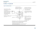
Страница 23: ...Operations Manual FGD MAN 0047 January 2017 13 Section 5 Operate Figure 5 1 Controller functionality ...
Страница 26: ...Operations Manual January 2017 FGD MAN 0047 16 ...
Страница 28: ...Operations Manual January 2017 FGD MAN 0047 18 ...
Страница 32: ...Operations Manual January 2017 FGD MAN 0047 22 ...
Страница 38: ...Operations Manual January 2017 FGD MAN 0047 28 ...
Страница 45: ...Operations Manual FGD MAN 0047 January 2017 35 ...
Страница 47: ...Operations Manual FGD MAN 0047 January 2017 37 ...
Страница 51: ...Operations Manual FGD MAN 0047 January 2017 41 ...
Страница 53: ...Notes ...
Страница 54: ...Notes ...
Страница 55: ......

