


iii
Figure 43 Shipping split detail, 625-750kVA, 12-pulse rectifier with bottom entry wireway. . . . . . . . . . . . 62
Figure 44 Battery power pack system . . . . . . . . . . . . . . . . . . . . . . . . . . . . . . . . . . . . . . . . . . . . . . . . . . . . . . . 63
Figure 45 Battery power pack, Size A. . . . . . . . . . . . . . . . . . . . . . . . . . . . . . . . . . . . . . . . . . . . . . . . . . . . . . . . 64
Figure 46 Line-up detail, 300-500kVA Single- or Multi-Module System with battery cabinets . . . . . . . . . . 65
Figure 47 Outline drawing, System Control Cabinet (SCCT), 200-1200A . . . . . . . . . . . . . . . . . . . . . . . . . . . 66
Figure 48 Base mounting patterns, System Control Cabinet (SCCT), 200-1200A . . . . . . . . . . . . . . . . . . . . 67
Figure 49 Outline drawing, System Control Cabinet (SCCT), 1600-2000A . . . . . . . . . . . . . . . . . . . . . . . . . . 68
Figure 50 Base mounting patterns, System Control Cabinet (SCCT), 1600-2000A . . . . . . . . . . . . . . . . . . . 69
Figure 51 Outline drawing, System Control Cabinet (SCCT), 2500-3000A . . . . . . . . . . . . . . . . . . . . . . . . . . 70
Figure 52 Base mounting patterns, System Control Cabinet (SCCT), 2500-3000A . . . . . . . . . . . . . . . . . . . 71
Figure 53 Outline drawing, System Control Cabinet (SCCT), 4000A . . . . . . . . . . . . . . . . . . . . . . . . . . . . . . 72
Figure 54 Base mounting patterns, System Control Cabinet (SCCT), 4000A . . . . . . . . . . . . . . . . . . . . . . . . 73
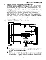
Figure 55 Control connection location diagram, Multi-Module System, 300-500kVA. . . . . . . . . . . . . . . . . . 74
Figure 56 Control connection location diagram, Multi-Module System, 625 & 750kVA . . . . . . . . . . . . . . . . 75
Figure 57 Control connection location diagram, SCCT . . . . . . . . . . . . . . . . . . . . . . . . . . . . . . . . . . . . . . . . . . 76
Figure 58 Control wiring, external interconnect diagram, Multi-Module System. . . . . . . . . . . . . . . . . . . . . 77
Figure 59 Control wire list, external interconnections, standard wiring, Multi-Module System,
UPS module, Cable Group #1. . . . . . . . . . . . . . . . . . . . . . . . . . . . . . . . . . . . . . . . . . . . . . . . . . . . . . 78
Figure 60 Control wire list, external interconnections, standard wiring, Multi-Module System,
System Control Cabinet, Part 1 of 3, Cable Groups #2 & #3 . . . . . . . . . . . . . . . . . . . . . . . . . . . . . 79
Figure 61 Control wire list, external interconnections, standard wiring, Multi-Module System,
System Control Cabinet, Part 2 of 3, Cable Groups #5 & #6 . . . . . . . . . . . . . . . . . . . . . . . . . . . . . 80
Figure 62 Control wire list, external interconnections, standard wiring, Multi-Module System,
System Control Cabinet, Part 3 of 3, Cable Group #8 . . . . . . . . . . . . . . . . . . . . . . . . . . . . . . . . . . 81
Figure 63 Control wire list, external interconnections, Multi-Module System, remote status panel
option, Cable Group #4 . . . . . . . . . . . . . . . . . . . . . . . . . . . . . . . . . . . . . . . . . . . . . . . . . . . . . . . . . . . 82
Figure 64 Control wire list, external interconnections, Multi-Module System (SCC with momentary
duty static switch), customer alarm interface option, Cable Group #9 . . . . . . . . . . . . . . . . . . . . . 83
Figure 65 Control wire list, external interconnections, Multi-Module System, alarm status contacts
option, Cable Group #14 . . . . . . . . . . . . . . . . . . . . . . . . . . . . . . . . . . . . . . . . . . . . . . . . . . . . . . . . . . 84
Figure 66 Control wire list, external interconnections, Multi-Module System, battery temperature
sensor option, Cable Group #15 . . . . . . . . . . . . . . . . . . . . . . . . . . . . . . . . . . . . . . . . . . . . . . . . . . . . 85
Figure 67 Control wire list, external interconnections, Multi-Module System, maintenance bypass
interlock option, Cable Group #7 . . . . . . . . . . . . . . . . . . . . . . . . . . . . . . . . . . . . . . . . . . . . . . . . . . . 86
Figure 68 Control wire list, external interconnections, Multi-Module System, SNMP interface option,
Cable Group #26 . . . . . . . . . . . . . . . . . . . . . . . . . . . . . . . . . . . . . . . . . . . . . . . . . . . . . . . . . . . . . . . . 87
Figure 69 Control wire list, external interconnections, Multi-Module System, Module 1/SCC,
Cable Groups #20 & #21 . . . . . . . . . . . . . . . . . . . . . . . . . . . . . . . . . . . . . . . . . . . . . . . . . . . . . . . . . . 88
Figure 70 Control wire list, external interconnections, Multi-Module System, Module 2/SCC,
Cable Groups #20 & #21 . . . . . . . . . . . . . . . . . . . . . . . . . . . . . . . . . . . . . . . . . . . . . . . . . . . . . . . . . . 89
Figure 71 Control wire list, external interconnections, Multi-Module System, Module 3/SCC,
Cable Groups #20 & #21 . . . . . . . . . . . . . . . . . . . . . . . . . . . . . . . . . . . . . . . . . . . . . . . . . . . . . . . . . . 90
Figure 72 Control wire list, external interconnections, Multi-Module System, Module 4/SCC,
Cable Groups #20 & #21 . . . . . . . . . . . . . . . . . . . . . . . . . . . . . . . . . . . . . . . . . . . . . . . . . . . . . . . . . . 91
Figure 73 Control wire list, external interconnections, Multi-Module System, Module 5/SCC,
Cable Groups #20 & #21 . . . . . . . . . . . . . . . . . . . . . . . . . . . . . . . . . . . . . . . . . . . . . . . . . . . . . . . . . . 92
Figure 74 Control wire list, external interconnections, Multi-Module System, Module 6/SCC,
Cable Groups #20 & #21 . . . . . . . . . . . . . . . . . . . . . . . . . . . . . . . . . . . . . . . . . . . . . . . . . . . . . . . . . . 93
Figure 75 Outline drawing, single-breaker module battery disconnect,
300, 450, 600, 800, 1000, 1200A . . . . . . . . . . . . . . . . . . . . . . . . . . . . . . . . . . . . . . . . . . . . . . . . . . . . 94
Figure 76 Outline drawing, single-breaker module battery disconnect,
1400AT/1600AT/2000AT/2500AT 600VDC circuit breaker . . . . . . . . . . . . . . . . . . . . . . . . . . . . . . 95
Figure 77 Outline drawing, dual-breaker module battery disconnect, 600, 800, 1000, 1200A . . . . . . . . . . . 96
Figure 78 Outline drawing, remote status panel, surface mount . . . . . . . . . . . . . . . . . . . . . . . . . . . . . . . . . . 97
Содержание Liebert Series 610
Страница 56: ...Installation Drawings 50 Figure 31 Base mounting patterns 500kVA module 6 pulse rectifier 88 797613 16 Rev 06 ...
Страница 57: ...Installation Drawings 51 Figure 32 Base mounting patterns 500kVA module 12 pulse rectifier 88 797613 22 Rev 04 ...
Страница 63: ...Installation Drawings 57 Figure 38 Shipping split detail 500kVA 12 pulse rectifier 88 797612 01 Rev 04 ...
Страница 65: ...Installation Drawings 59 Figure 40 Shipping split detail 625 750kVA 6 pulse rectifier 88 797612 04 Rev 04 ...
Страница 67: ...Installation Drawings 61 Figure 42 Shipping split detail 625 750kVA 12 pulse rectifier 88 797612 03 Rev 05 ...
Страница 69: ...Installation Drawings 63 Figure 44 Battery power pack system 88 797616 03 Rev 08 ...
Страница 70: ...Installation Drawings 64 Figure 45 Battery power pack Size A 88 797616 01 Rev 10 ...
Страница 72: ...Installation Drawings 66 Figure 47 Outline drawing System Control Cabinet SCCT 200 1200A 88 797614 01 Rev 08 ...
Страница 74: ...Installation Drawings 68 Figure 49 Outline drawing System Control Cabinet SCCT 1600 2000A 88 797614 02 Rev 07 ...
Страница 76: ...Installation Drawings 70 Figure 51 Outline drawing System Control Cabinet SCCT 2500 3000A 88 797614 03 Rev 08 ...
Страница 78: ...Installation Drawings 72 Figure 53 Outline drawing System Control Cabinet SCCT 4000A 88 797614 04 Rev 08 ...
Страница 82: ...Installation Drawings 76 Figure 57 Control connection location diagram SCCT 96 797619 88A Rev 04 ...
Страница 103: ...Installation Drawings 97 Figure 78 Outline drawing remote status panel surface mount 88 791617 01 Rev 05 ...
Страница 104: ...Installation Drawings 98 ...
Страница 109: ...Site Planning Data Series 610 500 750kVA Multi Module Systems 103 NOTES ...
Страница 110: ...Site Planning Data Series 610 500 750kVA Multi Module Systems 104 ...
Страница 111: ......