


i
TABLE OF CONTENTS
B
ATTERY
C
ABINET
P
RECAUTIONS
. . . . . . . . . . . . . . . . . . . . . . . . . . . . . . . . . I
NSIDE
F
RONT
C
OVER
C
ONTACTING
L
IEBERT
FOR
S
UPPORT
. . . . . . . . . . . . . . . . . . . . . . . . . . . . . . I
NSIDE
F
RONT
C
OVER
I
MPORTANT
S
AFETY
I
NSTRUCTIONS
. . . . . . . . . . . . . . . . . . . . . . . . . . . . . . . . . . . . . . . . . . . . . . . .1
1.0
I
NSTALLATION
C
ONSIDERATIONS
. . . . . . . . . . . . . . . . . . . . . . . . . . . . . . . . . . . . . . . . . . . . .3
1.1
Types of System Control Cabinets. . . . . . . . . . . . . . . . . . . . . . . . . . . . . . . . . . . . . . . . . . . . . . . 5
2.0
U
NLOADING
AND
H
ANDLING
. . . . . . . . . . . . . . . . . . . . . . . . . . . . . . . . . . . . . . . . . . . . . . . .6
3.0
I
NSPECTIONS
. . . . . . . . . . . . . . . . . . . . . . . . . . . . . . . . . . . . . . . . . . . . . . . . . . . . . . . . . . .7
3.1
External Inspections . . . . . . . . . . . . . . . . . . . . . . . . . . . . . . . . . . . . . . . . . . . . . . . . . . . . . . . . . 7
3.2
Internal Inspections and Shipping Material Removal . . . . . . . . . . . . . . . . . . . . . . . . . . . . . . . 7
4.0
E
QUIPMENT
L
OCATION
. . . . . . . . . . . . . . . . . . . . . . . . . . . . . . . . . . . . . . . . . . . . . . . . . . . .8
5.0
B
ATTERY
I
NSTALLATION
. . . . . . . . . . . . . . . . . . . . . . . . . . . . . . . . . . . . . . . . . . . . . . . . . . .9
5.1
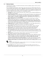
Battery Safety Precautions . . . . . . . . . . . . . . . . . . . . . . . . . . . . . . . . . . . . . . . . . . . . . . . . . . . . 9
5.2
Battery Safety Precautions in French Per CSA Requirements . . . . . . . . . . . . . . . . . . . . . . . 10
5.3
Battery Cabinets. . . . . . . . . . . . . . . . . . . . . . . . . . . . . . . . . . . . . . . . . . . . . . . . . . . . . . . . . . . . 11
5.4
Open-Rack Batteries . . . . . . . . . . . . . . . . . . . . . . . . . . . . . . . . . . . . . . . . . . . . . . . . . . . . . . . . 12
6.0
C
ONFIGURING
Y
OUR
N
EUTRAL
AND
G
ROUND
C
ONNECTIONS
. . . . . . . . . . . . . . . . . . . . . . .13
6.1
Preferred Grounding Configuration, Wye-Connected Service . . . . . . . . . . . . . . . . . . . . . . . . 14
6.2
Alternate Grounding Configuration, Wye-Connected Service . . . . . . . . . . . . . . . . . . . . . . . . 15
6.3
Preferred Grounding Configuration With Isolated Bypass . . . . . . . . . . . . . . . . . . . . . . . . . . 16
6.4
Alternate Grounding Configuration, Non-Isolated. . . . . . . . . . . . . . . . . . . . . . . . . . . . . . . . . 17
6.5
Grounding Configuration, Corner-Grounded Delta or Impedance-Grounded Wye . . . . . . . 18
6.6
Preferred Grounding Configuration, Battery Systems . . . . . . . . . . . . . . . . . . . . . . . . . . . . . 20
7.0
W
IRING
C
ONSIDERATIONS
. . . . . . . . . . . . . . . . . . . . . . . . . . . . . . . . . . . . . . . . . . . . . . . . .21
7.1
Power Wiring . . . . . . . . . . . . . . . . . . . . . . . . . . . . . . . . . . . . . . . . . . . . . . . . . . . . . . . . . . . . . . 22
7.2
Control Wiring . . . . . . . . . . . . . . . . . . . . . . . . . . . . . . . . . . . . . . . . . . . . . . . . . . . . . . . . . . . . . 24
7.3
Battery Wiring . . . . . . . . . . . . . . . . . . . . . . . . . . . . . . . . . . . . . . . . . . . . . . . . . . . . . . . . . . . . . 25
8.0
W
IRING
C
ONNECTIONS
. . . . . . . . . . . . . . . . . . . . . . . . . . . . . . . . . . . . . . . . . . . . . . . . . . .26
8.1
Specific Connections. . . . . . . . . . . . . . . . . . . . . . . . . . . . . . . . . . . . . . . . . . . . . . . . . . . . . . . . . 26
9.0
W
IRING
I
NSPECTION
. . . . . . . . . . . . . . . . . . . . . . . . . . . . . . . . . . . . . . . . . . . . . . . . . . . . .28
10.0 I
NSTALLATION
D
RAWINGS
. . . . . . . . . . . . . . . . . . . . . . . . . . . . . . . . . . . . . . . . . . . . . . . . .31
A
PPENDIX
A - S
ITE
P
LANNING
D
ATA
, S
ERIES
610, 500-750
K
VA, M
ULTI
-M
ODULE
S
YSTEMS
. . . . .99
Содержание Liebert Series 610
Страница 56: ...Installation Drawings 50 Figure 31 Base mounting patterns 500kVA module 6 pulse rectifier 88 797613 16 Rev 06 ...
Страница 57: ...Installation Drawings 51 Figure 32 Base mounting patterns 500kVA module 12 pulse rectifier 88 797613 22 Rev 04 ...
Страница 63: ...Installation Drawings 57 Figure 38 Shipping split detail 500kVA 12 pulse rectifier 88 797612 01 Rev 04 ...
Страница 65: ...Installation Drawings 59 Figure 40 Shipping split detail 625 750kVA 6 pulse rectifier 88 797612 04 Rev 04 ...
Страница 67: ...Installation Drawings 61 Figure 42 Shipping split detail 625 750kVA 12 pulse rectifier 88 797612 03 Rev 05 ...
Страница 69: ...Installation Drawings 63 Figure 44 Battery power pack system 88 797616 03 Rev 08 ...
Страница 70: ...Installation Drawings 64 Figure 45 Battery power pack Size A 88 797616 01 Rev 10 ...
Страница 72: ...Installation Drawings 66 Figure 47 Outline drawing System Control Cabinet SCCT 200 1200A 88 797614 01 Rev 08 ...
Страница 74: ...Installation Drawings 68 Figure 49 Outline drawing System Control Cabinet SCCT 1600 2000A 88 797614 02 Rev 07 ...
Страница 76: ...Installation Drawings 70 Figure 51 Outline drawing System Control Cabinet SCCT 2500 3000A 88 797614 03 Rev 08 ...
Страница 78: ...Installation Drawings 72 Figure 53 Outline drawing System Control Cabinet SCCT 4000A 88 797614 04 Rev 08 ...
Страница 82: ...Installation Drawings 76 Figure 57 Control connection location diagram SCCT 96 797619 88A Rev 04 ...
Страница 103: ...Installation Drawings 97 Figure 78 Outline drawing remote status panel surface mount 88 791617 01 Rev 05 ...
Страница 104: ...Installation Drawings 98 ...
Страница 109: ...Site Planning Data Series 610 500 750kVA Multi Module Systems 103 NOTES ...
Страница 110: ...Site Planning Data Series 610 500 750kVA Multi Module Systems 104 ...
Страница 111: ......