


Unloading and Handling
6
2.0
U
NLOADING
AND
H
ANDLING
With the exception of the 500kVA unit with 6-pulse rectifier, UPS modules are shipped in split cabi-
nets to allow ease of handling. Because the weight distribution in the cabinets is uneven, use extreme
care during handling and transport. Your installation may also include battery cabinets and a System
Control Cabinet.
To reduce the possibility of shipping damage, cabinets are shored with 2-by-4 bracing, secured with
screw-type nails. This shoring must be carefully removed prior to unloading.
NOTE
It is very important that the shipping split sections are matched up to their proper mates, as
identified by the shipping split labels.
Integrated SCC/Switchgear will also be shipped in sections, and require proper match up of
sections, as identified by labels and drawings.
!
WARNING
Exercise extreme care when handling UPS cabinets to avoid equipment damage or injury to
personnel. The UPS module weight ranges from 5710 to 12,005 lbs. (2590 to 5445kg). Battery
cabinets weigh from 3060 to 5300 lbs. (1388 to 2404kg).
Locate center of gravity symbols before handling cabinet. Test lift and balance the cabinet
before transporting. Maintain minimum tilt from vertical at all times.
Slots at the base of the modules and battery cabinets are intended for forklift use. Base slots
will support the unit only if the forks are completely beneath the unit.
System Control Cabinets (SCCs)/Switchgear have holes intended for rigging bars or chains
(see your submittal package for switchgear drawings). Prevent chains or cables from
contacting cabinet by using spreader bar and adequate padding.
!
CAUTION
Extreme care is necessary when removing shoring braces. Do not strike cabinet with
hammers or other tools.
Содержание Liebert Series 610
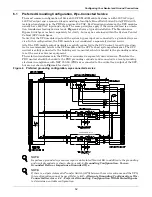
Страница 56: ...Installation Drawings 50 Figure 31 Base mounting patterns 500kVA module 6 pulse rectifier 88 797613 16 Rev 06 ...
Страница 57: ...Installation Drawings 51 Figure 32 Base mounting patterns 500kVA module 12 pulse rectifier 88 797613 22 Rev 04 ...
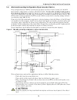
Страница 63: ...Installation Drawings 57 Figure 38 Shipping split detail 500kVA 12 pulse rectifier 88 797612 01 Rev 04 ...
Страница 65: ...Installation Drawings 59 Figure 40 Shipping split detail 625 750kVA 6 pulse rectifier 88 797612 04 Rev 04 ...
Страница 67: ...Installation Drawings 61 Figure 42 Shipping split detail 625 750kVA 12 pulse rectifier 88 797612 03 Rev 05 ...
Страница 69: ...Installation Drawings 63 Figure 44 Battery power pack system 88 797616 03 Rev 08 ...
Страница 70: ...Installation Drawings 64 Figure 45 Battery power pack Size A 88 797616 01 Rev 10 ...
Страница 72: ...Installation Drawings 66 Figure 47 Outline drawing System Control Cabinet SCCT 200 1200A 88 797614 01 Rev 08 ...
Страница 74: ...Installation Drawings 68 Figure 49 Outline drawing System Control Cabinet SCCT 1600 2000A 88 797614 02 Rev 07 ...
Страница 76: ...Installation Drawings 70 Figure 51 Outline drawing System Control Cabinet SCCT 2500 3000A 88 797614 03 Rev 08 ...
Страница 78: ...Installation Drawings 72 Figure 53 Outline drawing System Control Cabinet SCCT 4000A 88 797614 04 Rev 08 ...
Страница 82: ...Installation Drawings 76 Figure 57 Control connection location diagram SCCT 96 797619 88A Rev 04 ...
Страница 103: ...Installation Drawings 97 Figure 78 Outline drawing remote status panel surface mount 88 791617 01 Rev 05 ...
Страница 104: ...Installation Drawings 98 ...
Страница 109: ...Site Planning Data Series 610 500 750kVA Multi Module Systems 103 NOTES ...
Страница 110: ...Site Planning Data Series 610 500 750kVA Multi Module Systems 104 ...
Страница 111: ......