


Instruction Manual
D103425X012
546NS Transducer
June 2021
18
2. Check zero and span adjustment for proper setting. Refer to the adjustments procedure.
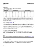
3. Check the supply pressure. It should be at least 0.3 bar (5 psig) above the upper limit of the output pressure range.
4. Check the filter regulator for moisture in the dripwell. Drain off any moisture, and clean the filter element if
necessary.
and that the tubing is not plugged.
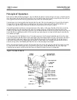
6. Check the nozzle. If it is clogged, remove the entire torque motor assembly from the case by removing four
machine screws (key 9, figure 7). Run a wire through the nozzle from the underside of the assembly.
7. Erratic operation may be caused by metal chips in the air gap between the armature and the pole pieces. Blow any
chips out of the torque motor assembly with low pressure air.
8. A short in the coils may cause the device to give zero output. Return the device to a Fisher service center for repair.
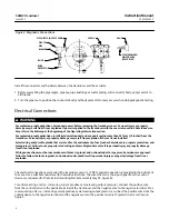
WARNING
Severe personal injury or property damage may occur if the instrument air supply is not clean, dry and oil‐free. While use
and regular maintenance of a filter that removes particles larger than 40 micrometers in diameter will suffice in most
applications, check with an Emerson Automation Solutions field office and industry instrument air quality standards for use
with corrosive air or if you are unsure about the proper amount or method of air filtration or filter maintenance.
9. Check the nozzle for residue. Air supply must be clean and dry. Use air filter to remove dirt and oil.
10. Check the pneumatic connection of the transducer to prevent leakage.
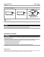
Alignment
The following alignment procedures can be used in conjunction with troubleshooting procedures to correct the
operation of a faulty transducer.
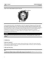
Span Adjustment
Refer to figure 8 for key number locations, unless otherwise directed.
If setting the required span is not possible, additional span adjustment can be obtained by shifting the entire span
adjustment assembly (key 55) at the flexure pivot end. The alignment procedure is as follows:
1. Shut off the DC input signal and supply pressure to the transducer.
2. Disconnect the external lead wires from the terminal mounting bracket assembly (key 53).
entire torque motor assembly from the case.
4. Loosen the two flexure pivot screws (key 25) that hold the flexure pivot to the torque motor assembly base.
5. Slide the span adjustment assembly in or out as required. Sliding it in toward the base decreases the span; sliding it
out away from the base increases the span.
sure that the O‐ring (key 37) is in place. Connect the external lead wires, and turn on the air supply.
7. Make final adjustment of the span with the span adjustment screw.


