Instruction Manual
D200149X012
3610J and 3620J Positioners
September 2017
20
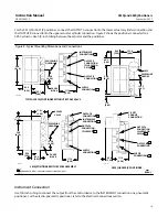
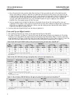
Figure 8. Typical Mounting Dimensions and Connections (Continued)
19A1486‐C
11B2613‐C
B2151‐2
208
(8.19)
146
(5.75)
93.0
(3.66)
63.5
(2.50)
63.5
(2.50)
63.5
(2.50)
146
(5.75)
50.8
(2.00)
100
(3.95)
208
(8.19)
87.4
(3.44)
153.9
(6.06)
49.3
(1.94)
3621JP POSITIONER
3611JP POSITIONER
SUPPLY
CONNECTION
OUTPUT B
CONNECTION
SUPPLY
CONNECTION
OUTPUT B
CONNECTION
OUTPUT A
CONNECTION
INSTRUMENT
CONNECTION
OUTPUT A
CONNECTION
1/2 NPT
CONDUIT
CONNECTION
NOTE:
1INSTRUMENT, OUTPUT, AND SUPPLY CONNECTIONS ARE 1/4 NPT
3622 I/P
CONVERTER
GAUGE
BLOCK
CENTERLINE
OF BODY
17.5
(0.69)
1
1
1
1
1
1
1
Diagnostic Connections
To support diagnostic testing of valve/actuator/positioner/accessory packages, special connectors and hardware are
available. The hardware used includes 1/8 NPT connector bodies and body protectors. If the diagnostic connectors are
ordered for a positioner with gauges, 1/8‐inch stems are also included.
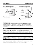
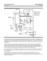
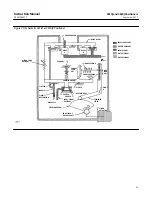
Install the connectors on the 3610J positioner gauge block or bypass block assembly as shown in figure 9. For 3620J
positioners, install the connectors on the 3622 housing as shown in figure 10. Before installing the connectors on the
positioner, apply sealant to the threads. Sealant is provided with the diagnostic connections and hardware.

