


User Manual
Chapter 5
GFK-1742F
Jan 2020
DSM314 to Host Controller Interface
136
limit is zero for negative motion. Negative Only means that the velocity limit is zero
for positive motion. No error is generated for the limit that is set to zero. For
example, if Command Direction is set to Negative Only and + Counts are
commanded, the Velocity Limit Status bit is set, but no Status Error code is reported.
1.17 Follower Ramp Active. When the follower is enabled, Follower Ramp Active is ON
during initial acceleration and distance makeup. When the follower is disabled,
Follower Ramp Active is ON until the Follower Disable Action incremental distance
(if selected) has been traveled and the follower has decelerated to zero velocity.
5.2
Section 2: %AI Status Words
The following %AI Status Words are transferred automatically from the DSM314 to the CPU
each sweep. The total number of the %AI Status Words is configured with the Configuration
Software to be a length of 24, 44, 64 or 84. The actual addresses of the Status Words depend
on the starting address configured for the %AI references. See Table 40
, “Settings Tab.” The
word numbers listed in the following table are offsets to this starting address. All reference
section designations pertain to this chapter. All %AI data except Actual Velocity is updated
within the DSM314 at the position loop sampling rate (2 ms for digital servos, 0.5 ms or 1.0
ms for some analog servo configurations). Actual Velocity is updated once every 128
milliseconds.
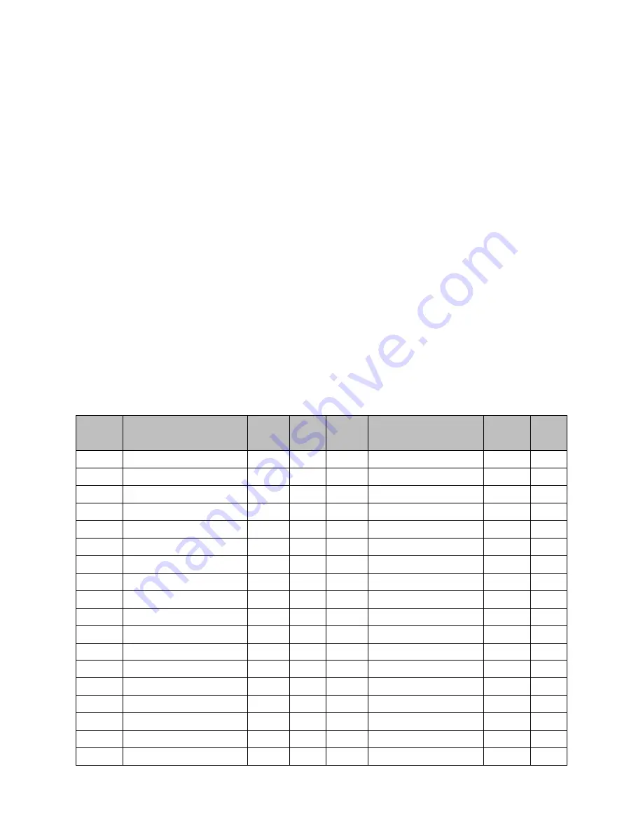
Table 43: %AI Status Words
Word
Offset
Description
Axis
Ref
Word
Offset
Description
Axis
Ref
00
Module Status Code
N/A
2.01
01-03
Reserved
04
Axis 1 Error Code
Servo 1 2.02
44
Axis 3 Error Code
Servo 3
2.02
05
Command Block Number
Servo 1 2.03
45
Command Block Number Servo 3
2.03
06-07
Commanded Position
Servo 1 2.04
46-47
Commanded Position
Servo 3
2.04
08-09
Actual Position
Servo 1 2.05
48-49
Actual Position
Servo 3
2.05
10-11
Strobe 1 Position
Servo 1 2.06
50-51
Strobe 1 Position
Servo 3
2.06
12-13
Strobe 2 Position
Servo 1 2.06
52-53
Strobe 2 Position
Servo 3
2.06
14-15
Position Error
Servo 1 2.07
54-55
Position Error
Servo 3
2.07
16-17
Commanded Velocity
Servo 1 2.08
56-57
Commanded Velocity
Servo 3
2.08
18-19
Actual Velocity
Servo 1 2.09
58-59
Actual Velocity
Servo 3
2.09
20-21
User Selected Data 1
Servo 1 2.10
60-61
User Selected Data 1
Servo 3
2.10
22-23
User Selected Data 2
Servo 1 2.11
62-63
User Selected Data 2
Servo 3
2.11
24
Axis 2 Error Code
Servo 2 2.02
64
Axis 4 Error Code
Servo 4
2.02
25
Commanded Block Number Servo 2 2.03
65
Command Block Number Servo 4
2.03