94
100-412-183 REV. 13
7.4
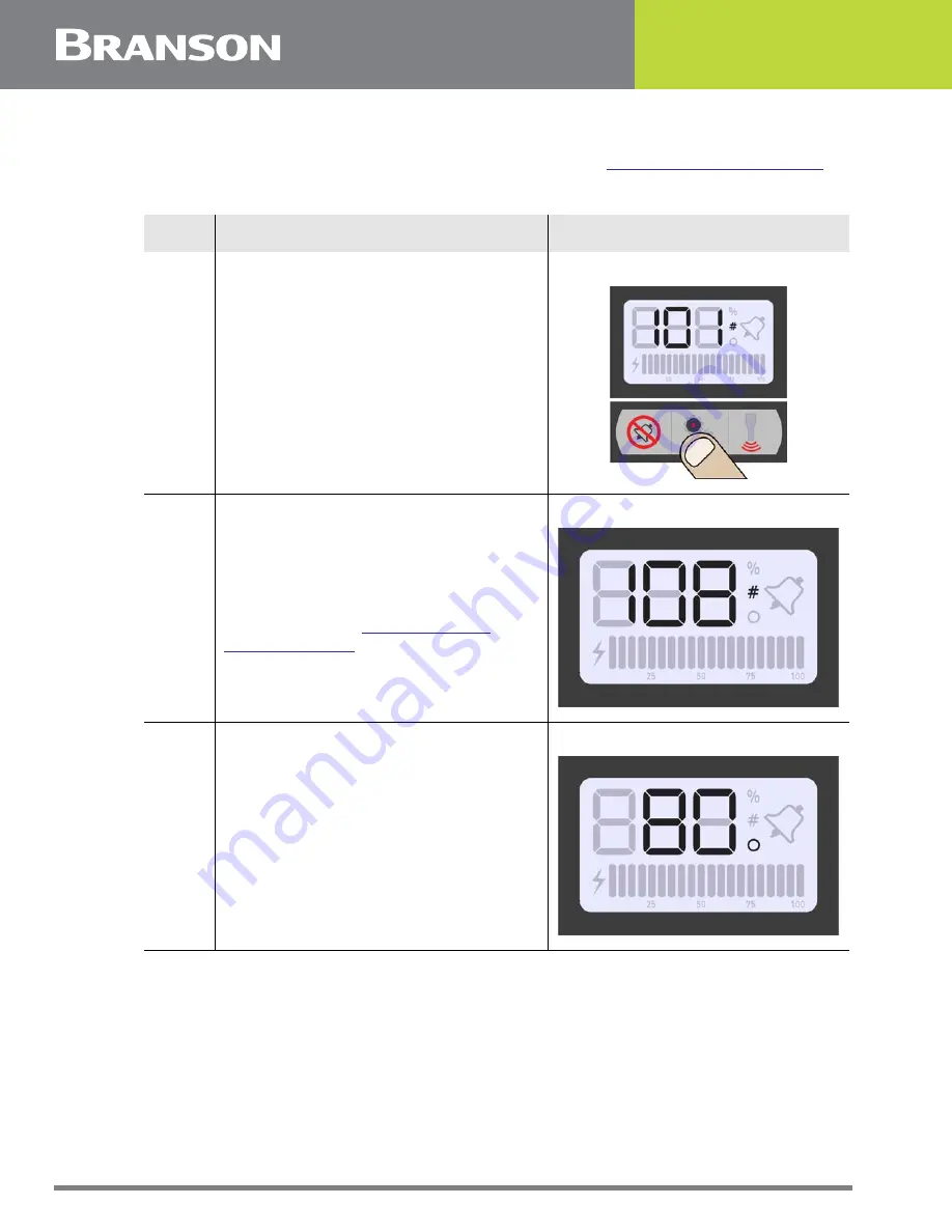
Configuring the Power Supply Registers
At power up the DCX S Power Supply will display the last amplitude setting, this is
indicated by the percentage icon (%) on the LCD. Refer to
Table 7.3
Steps to configure the Power Supply Registers
Step
Action
Reference
1
Press the Configuration key until the
number icon (#) appears on the LCD.
The power supply will display register
101 the first time you access the
registers. (If you access the registers
again the last selected register will be
displayed).
2
Press and release the Up or Down arrow
keys to select the desired register. For a
detailed description of available
registers refer to
.
3
Once you have reached the desired
register, press the Configuration key.
The register value will be displayed, this
is indicated by the circle icon.
Содержание DCX S
Страница 4: ...iv 100 412 183 REV 13 ...
Страница 14: ...4 100 412 183 REV 13 Figure 1 2 Safety related Labels found on the DCX S Power Supply Vertical ...
Страница 22: ...12 100 412 183 REV 13 ...
Страница 36: ...26 100 412 183 REV 13 ...
Страница 47: ...100 412 183 REV 13 37 4 3 Declaration of Conformity Figure 4 1 Declaration of Conformity ...
Страница 50: ...40 100 412 183 REV 13 ...
Страница 54: ...44 100 412 183 REV 13 Figure 5 1 DCX S Power Supply Benchtop Dimensional Drawing ...
Страница 86: ...76 100 412 183 REV 13 ...
Страница 87: ...100 412 183 REV 13 77 Chapter 6 Converters and Boosters 6 1 Converters and Boosters 78 ...
Страница 120: ...110 100 412 183 REV 13 ...
Страница 137: ...100 412 183 REV 13 127 8 5 Circuit Diagram Figure 8 2 Interconnect Diagram Power Supply ...
Страница 144: ...134 100 412 183 REV 13 ...
Страница 145: ...100 412 183 REV 13 135 Appendix A Timing Diagrams A 1 Timing Diagrams 136 ...
Страница 146: ...136 100 412 183 REV 13 A 1 Timing Diagrams Figure A 1 Weld Cycle Figure A 2 Weld Cycle Figure A 3 Weld Cycle ...
Страница 147: ...100 412 183 REV 13 137 Appendix B Signal Diagrams B 1 Signal Diagrams 138 ...
Страница 154: ...144 100 412 183 REV 13 ...


