

18
C6.2.24/1014-0215/E
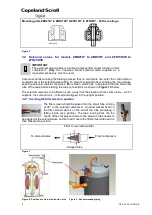
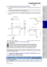
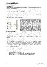
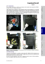
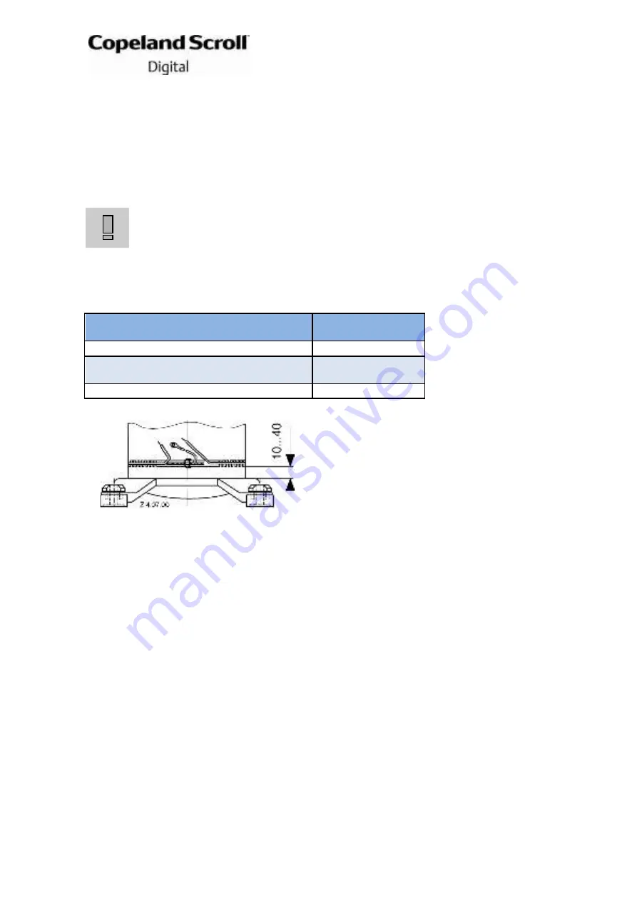
Figure 21: Crankcase heater location
4.2.3 Motor protection
For ZBD21K* to ZBD114K*, ZFD13KVE to ZFD25KVE and ZFD41K5E compressors,
conventional inherent internal line break motor protection is provided.
4.2.4 Protection devices
Independently from the internal motor protection, fuses must be installed before the compressor.
Selection of fuses has to be carried out according to VDE 0635, DIN 57635, IEC 269-1 or
EN 60-269-1.
4.2.5 Crankcase heaters
IMPORTANT
Oil dilution! Bearing malfunction!
Turn the crankcase heater on 12 hours
before starting the compressor.
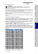
A crankcase heater is used to prevent refrigerant migrating into the shell during standstill
periods.
Due to the Copeland scroll’s inherent ability to handle liquid refrigerant in flooded
conditions a crankcase heater is not required when the system charge does not exceed the
charge limits shown in
Table 7
.
Compressor
Refrigerant charge
limit
ZBD21K* & ZBD29K*
3.6 kg
ZBD30K* to ZBD57K*
ZFD13KVE to ZFD25KVE
4.5 kg
ZBD58K* to ZBD114K* & ZFD41K5E
7.5 kg
Table 7
If a crankcase heater is fitted it is recommended
that the heater be turned on for a
minimum of 12
hours
prior to starting the compressor. This will
prevent oil dilution and bearing stress on initial
start-up. The crankcase heater must remain
energised during compressor off cycles.
The crankcase heater must be mounted below the
oil Schraeder valve located on the bottom shell (see
Figure 24
).
The crankcase heater should be wired in such a way that it is turned on whenever the
compressor is switched off.
4.3 Pressure safety controls
4.3.1 IPR valve (Internal Pressure Relief valve)
The internal pressure relief valves for models ZBD21K* to ZBD57K* and ZFD13KVE to
ZFD25KVE are located between the high and low sides of the compressor. They are designed to
open when the discharge-to-suction differential pressure exceeds 26-31 bar. When the valve
opens, hot discharge gas is routed back into the area of the motor protector to cause a trip.
During developmental blocked fan testing, it is sometimes noted that the valve opens, but the
compressor does not shut off while the discharge pressure continues to climb. This condition is
normally caused by flood back and may be corrected by using a more restrictive expansion
device or reducing the refrigerant charge.
ZBD58K* to ZBD114K* and ZFD41K5E compressors do not have internal pressure relief valves.
To ensure safe operation, a high-pressure control must be used in all applications with this
compressor. This pressure control will act independently of the digital controller.
4.3.2 High-pressure control
A high-pressure control with a maximum cut-out setting of 28 bar(g) is required.
The high-pressure control should have a manual reset feature for the highest level of system
protection.


