background image


© 2017 Emerson Climate Technologies, Inc.


AE21-1355 R4 


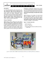
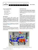
Figure 5 Copeland(R) Digital Compressor Controller 


Control Requirements with Copeland

 Digital 

Compressor Controller 

The  Digital  Compressor  Controller  is  an  electronics 
interface  between  the  Copeland 

Discus 

digital 

compressor  and  the  system  controller.  The  system 
controller measures temperature or pressure to calculate 
the needed compressor capacity and communicates that 
capacity  to  the  Digital  Compressor  Controller  via  an 
analog signal.  


NOTE:

  For  more  information  on  the  Copeland  Digital 

Compressor Controller refer to the application guidelines 
i

AE8-1328

,


Copeland Digital Compressor Controller

Four  #10  self  tapping  sheet  metal  screws,  at  least  ½” 
length,  are  required  for  installation.  The  maximum 
mounting  screw  torque  is  20  in.  lbs.  Locate  the  Digital 
Compressor  Controller  inside  the  electrical  enclosure 
near  the  compressor  contactor  (wire  routing  for 
compressor power wiring will be easier in this position). 
The maximum wire terminal screw torque is 7 in. lbs. The 
Digital  Compressor  Controller  will  operate  in  any 
mounting orientation where the green POWER LED is 
at  the  top.  Mount  the  Digital  Compressor  Controller 
such  that  all  LEDs  are  visible  from  a  comfortable 
viewing  position.  A  service  panel  label  (

Form 

Numbers: 052-2401- 00, 052-2402-00, and 052-2843-
00

) describing the terminals and ALERT flash codes is 

included with each Digital Compressor Controller. This 
label should be in a visible location for the technician 
when troubleshooting the system. 
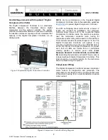
Compressor Wiring 

The Digital  Compressor Controller senses compressor 
motor  current  for  diagnostics  and  protection.  The 
compressor motor leads must be run through the holes 
in the plastic housing for a current transformer to sense 
motor current. 


Figure 6 Compressor Controller Wiring Diagram


Содержание COPELAND 3DSDR17ME-TFD

Страница 1: ... and More Information 10 TABLE OF FIGURES Figure 1 Copeland Discus Digital Unloaded Operation Shown on a Copeland 3D Discus 4 Figure 2 Copeland Discus Digital Loaded View shown on a Copeland 3D Discus 5 Figure 3 Typical Modulated Power Reduction for 3D Discus Digital 6 Figure 4 Loaded vs Time 6 Figure 5 Copeland R Digital Compressor Controller 7 Figure 6 Compressor Controller Wiring Diagram 7 Revi...

Страница 2: ... lifetime of the compressor You are strongly advised to follow these safety instructions Safety Icon Explanation DANGER indicates a hazardous situation which if not avoided will result in death or serious injury WARNING indicates a hazardous situation which if not avoided could result in death or serious injury CAUTION used with the safety alert symbol indicates a hazardous situation which if not ...

Страница 3: ...and refrigeration oils Personal safety equipment must be used Failure to follow these warnings could result in serious personal injury BURN HAZARD Do not touch the compressor until it has cooled down Ensure that materials and wiring do not touch high temperature areas of the compressor Use caution when brazing system components Personal safety equipment must be used Failure to follow these warning...

Страница 4: ...he 3D By varying the percentage of duty cycle that the compressor is loaded and unloaded capacity control between 10 and 100 can be achieved During blocked suction operation the flow of suction gas is blocked to all cylinders on a single bank therefore there is no gas to compress and the power consumption is significantly lower The unloader piston mechanism that controls flow of suction gas into t...

Страница 5: ...iscus compressor envelopes The head fan return gas and oil cooler requirements are the same as those for the standard Discus compressors Control Capacity modulation is achieved by energizing and de energizing the solenoid valve When the solenoid valve is de energized the compressor capacity is 100 When the solenoid valve is energized the compressor capacity is zero Therefore the capacity achieved ...

Страница 6: ... 2017 Emerson Climate Technologies Inc 6 AE21 1355 R4 Figure 3 Typical Modulated Power Reduction for 3D Discus Digital Figure 4 Loaded vs Time ...

Страница 7: ... Digital Compressor Controller inside the electrical enclosure near the compressor contactor wire routing for compressor power wiring will be easier in this position The maximum wire terminal screw torque is 7 in lbs The Digital Compressor Controller will operate in any mounting orientation where the green POWER LED is at the top Mount the Digital Compressor Controller such that all LEDs are visib...

Страница 8: ... Emerson com OPI The compressor motor should only be restarted after an appropriate time delay The digital modulation cycle time recommended is 20 seconds for other values check with your Application Engineer The minimum load and unload times should be limited to 2 seconds These described load and unload times will give the compressor an operating range during a 20 second cycle from 10 load up to ...

Страница 9: ...e on a 4D you have continuous capacity from 50 to 100 therefore when selecting a 4D digital compressor you should have a fixed compressor behind it that is 50 100 of the full load of the digital compressor Example1 You have selected a 4DAXF47KL TSK This compressor capacity is about 47 000 Btu per hour 50 capacity is about 23 500 Then D 47 000 BTU h As the first fixed capacity compressor you must c...

Страница 10: ...ow or contact your Application Engineer AE4 1135 Cooling Requirements for Copelametic and Copeland Discus Compressors AE4 1287 Copeland Discus Demand Cooling AE4 1334 Low Condensing Temperature Bulletin AE8 1328 Copeland Digital Compressor Controller AE8 1368 CoreSense Diagnostics v2 11 for Copeland Discus Compressors AE4 1357 Upgrade Procedures for Parallel Applications Using Digital Capacity Con...

Страница 11: ...4012 167 C 0 01250 15 C 8 29400 30 C 0 80560 75 C 0 14800 120 C 0 03900 168 C 0 01226 14 C 6 89570 31 C 0 77200 76 C 0 14310 121 C 0 03793 169 C 0 01203 13 C 6 52190 32 C 0 74010 77 C 0 13850 122 C 0 03690 170 C 0 01180 12 C 6 17110 33 C 0 70960 78 C 0 13400 123 C 0 03590 171 C 0 01157 11 C 5 84150 34 C 0 68060 79 C 0 12970 124 C 0 03494 172 C 0 01134 10 C 5 53190 35 C 0 65300 80 C 0 12550 125 C 0...

Отзывы: