background image

Installation 

Avtron Model LPH400  •  Resistive Load Bank 

Part Number LPH400D30693-1 


3-5 


LOAD CONNECTION


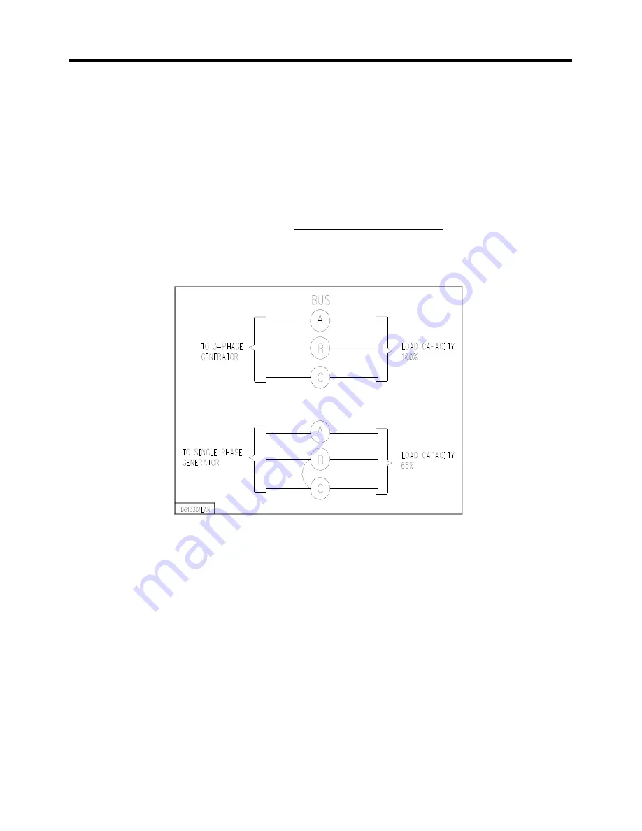
Connect a 240/480 volt, 3-phase source to the three fused bars labeled A, B and C, located in the 
customer connection access box.  Cables to the Load Bank should be sized to handle the 
maximum rated load according to the National Electric Code.  Verify load cables, lugs, and 
mounting hardware have sufficient arc over clearance to sheet metal and cover when closed.  The 
current can be determined by the following formula: 


Line Current  = 

kW  

× 

 577 

VOLTAGE (Line to Line) 


    ************************************************************* 


W A R N I N G


"B" Bus and any attached wiring are electrically hot when 
operating Load Bank in single phase. 


    ************************************************************* 


Содержание AVTRON LOADBANK LPH400

Страница 1: ...AVTRON MODEL LPH400 RESISTIVE LOAD BANK Part Number LPH400D30693 1 2009 Avtron Loadbank Inc April 12 2000 Cleveland Ohio Rev Aug 18 2009 ...

Страница 2: ......

Страница 3: ...ic Load Bank D27552 Resistor Assembly D27553 Resistor Assembly D27555 Resistor Assembly SUPPLEMENTAL VENDOR MANUALS Provided Separately Electro Industries SHARK100 Installation and Operation Manual Gauge Tech CD ROM E145420 For Load Banks S N s 375 and above Electro Industries Quick Start Guide for SHARK Series Meters E145703 Gauge Tech For Load Banks S N s 375 and above Electro Industries DMMS 30...

Страница 4: ...ducted to ensure the reliability and safety built into your Avtron equipment The Model LPH400 Load Banks are industrial test units designed for safe use indoors However because the Load Bank s function is to dissipate electrical energy there are inherent dangers to the operators and to the equipment These dangers shall be outlined in this section Electrical energy is transformed into heat by the r...

Страница 5: ... the unit to cool the elements Do not allow the unit to be placed where hot exhaust air can recirculate back through the unit causing a constant rise in cooling air temperature 10 After running a load test residual heat should be removed from the Load Bank by allowing the fan to operate for a few minutes after load is removed This procedure is not required for maintaining Load Bank integrity but i...

Страница 6: ...ling any heated elements B The power ON OFF switch will disconnect both load steps and fan motor A customer supplied Generator Emergency OFF switch should be located near the Load Bank 17 An approved electrical fire extinguisher should be on hand at all times 18 It is the responsibility of the customer to take diligent care in installing the Load Bank The National Electrical Code NEC sound local e...

Страница 7: ...ource under test the motor circuit connects the motor for high or low voltage The unit will test 240 480 volt 3 phase 60 Hz generators without any wiring changes It can be used to test 60 Hz 50 Hz or 400 Hz generators however the fan motor and control circuit power must be supplied by separate 60 Hz sources when testing 50 Hz or 400 Hz generators For separate 60 Hz fan motor power connection see S...

Страница 8: ...the load connection compartment Customer Connection Access Box The Load Bank can operate at either 480 or 240 volts A switch on the control panel S7 will switch the load from the high voltage configuration to the low voltage configuration The fan motor configuration also changes if powered from generator under test The fan motor has separate overload protection for high and low voltage operation T...

Страница 9: ...s operated in a closed space ventilation of 11 000 CFM or greater is required Temporary outdoor use is acceptable if climate and environment are suitable Some moisture from light non freezing rain will not damage the unit if running or in storage outdoors with control panel slide cover door shut A minimum of four feet of clearance from the inlet end and eight feet of clearance on the exhaust end a...

Страница 10: ...in positioning the Load Banks so that the exhausted air of one unit does not feed the air intake of another 2 RESTRICTION OF COOLING AIR Any obstruction located within four 4 feet of the inlet or eight 8 feet of exhaust screens will restrict the Load Bank s airflow Airflow is also restricted when two or more Load Banks have air inlets positioned close to each other This competition for cooling air...

Страница 11: ...the operator applies either 240V or 480V to the primary the control transformer supplies 120 VAC for control power An external power source must be provided as described in section B of Fan Motor Connections if internal power for motor and control power is not desired During startup be sure the load switch on the generator under test is not ON until the prime mover has the generator up to speed Al...

Страница 12: ...Fan motor will operate between 208 and 250 volts and between 416 and 500 volts at 3 phase 60 Hz Connection at 50 Hz is the same as 60 Hz with motor voltage range of 180 to 220 volts and 360 to 440 volts W A R N I N G When operating at 50 Hz the motor speed RPM is reduced which also reduces cooling of the Load Bank Do not exceed 400 volts in the 480 mode or 200 volts in the 240 mode to input bus wh...

Страница 13: ...bles to the Load Bank should be sized to handle the maximum rated load according to the National Electric Code Verify load cables lugs and mounting hardware have sufficient arc over clearance to sheet metal and cover when closed The current can be determined by the following formula Line Current kW 577 VOLTAGE Line to Line W A R N I N G B Bus and any attached wiring are electrically hot when opera...

Страница 14: ...and a good earth ground The ground conductor should be sized for National Electric Code Table 250 122 if not superseded by local codes W A R N I N G Do not operate the Load Bank with any panel or screen removed This may expose the operator to dangerous high voltage and the rotating fan blade as well as disrupting the airflow Keep the hinged cover on connection access box closed and latched STORAGE...

Страница 15: ...tch When Option 1 is installed this switch is used to set correct input voltage to the Control Transformer This method should be used only if voltage and frequency of the generator under test falls within the ranges specified in the INSTALLATION section 5 BLOWER START STOP Pushbuttons Pushbuttons are used to initiate fan motor start and stop circuits 6 FAN ROTATION ABC CBA Switch This switch is us...

Страница 16: ...n 1 is included Then no line cord and no action required here 2 Connect the unit to be tested as described in Section III INSTALLATION under Power Requirements Use all three load bus bars in the customer connection access box for 3 phase generators or connect the power cables to the Phase A and Phase C bus bars for single phase generators See Section III INSTALLATION for details C A U T I O N The ...

Страница 17: ...ss the BLOWER START pushbutton Verify air flow is in the correct direction If not shut down fan by depressing the STOP pushbutton Wait until fan blade stops rotating then switch fan rotation switch ABC CBA Restart and verify airflow Upon energizing the fan the red BLOWER FAIL lamp will light momentarily until the air switch detects sufficient cooling air at which time it will go out applying power...

Страница 18: ... volts 14 To remove load move MASTER LOAD switch to OFF position 15 Shutdown Reverse steps 1 through 12 It is good procedure to allow the fan motor to operate for about 5 minutes after the load is removed This will exhaust any accumulated heat and allow exhaust surfaces to cool Although not required for maintaining Load Bank integrity the cooling procedure helps to prevent burn injuries W A R N I ...

Страница 19: ...LPH400 Resistive Load Bank Part Number LPH400D30693 1 4 5 C A U T I O N Never exceed the rated voltage This will cause the Load Bank to overheat Do not apply DC voltages because the contactors do not have arc blowout magnets ...

Страница 20: ...at the top of this page Put on a grounded wrist strap before handling any ESD sensitive item Clear work area of Styrofoam plastic and vinyl items such as coffee cups Handle ESD items by the body never the open edge connectors Never slide ESD sensitive items over any surface Transport ESD sensitive items in a static shielding container to a static free work station If a static free work station is ...

Страница 21: ... maintain the equipment in a good safe condition All maintenance work must be done by qualified personnel only W A R N I N G Personal injury from electrical shock or from the rotating fan blade may result if ALL sources of power are not disconnected before servicing Refer to Section I SAFETY CONSIDERATIONS of this manual DAILY 1 Remove any Load Bank airflow restrictions 2 Check the screens to make...

Страница 22: ...ll contactors to make sure that the contacts are not severely pitted or corroded The contacts must move freely and be properly seated 8 Clean all dirt and debris out of the Load Bank This can be accomplished by blowing the inside of the unit with clean dry compressed air W A R N I N G Use only clean dry compressed air not to exceed 40 PSI Eye protection must be worn when cleaning with compressed a...

Страница 23: ...ads are terminated properly 12 Replace all access panels and screens Tighten all the fastening hardware securely 13 Check the indicator lamps on the control panel and replace as necessary ANNUALLY The blower motor must be lubricated per the motor manufacturer s requirements and specifications on the motor nameplate PARTS REPLACEMENT Access to any component is easily made with the removal of the co...

Страница 24: ...nges are sometimes necessary and revisions to the parts list may be made at any time without notice REFERENCE DESIGNATORS Service personnel may use this parts list along with the Avtron system schematics to identify and order replaceable parts The reference designators were carefully selected and matched to those on the schematic diagrams and equipment to simplify the troubleshooting and repair pr...

Страница 25: ...0 CONDUCTOR 364874 4 RESISTOR ASSEMBLY D27552 3 1 K1 3A B RELAY 3P 25A 110 120V B14795 3 50 60HZ COIL PER AVTRON DWG K4B RELAY 3P 50A 110 120V 50 60 HZ COIL B14796 1 PER AVTRON DWG XF4 6 10 12 FUSEBLOCK 3 POLE 60 AMP 600V 324660 2 FOR 1 56 X 812 DIA FUSE F4 6 10 12 FUSE CARTRIDGE 40 AMP 600V VERY FAST ACTING 324419 6 RESISTOR ASSEMBLY D27552 1 1 K1 3A RELAY 3P 25A 110 120V B14795 3 50 60 HZ COIL P...

Страница 26: ...G INSULATOR 562 005 OD 385 411146 24 005 ID 1 130 010 LG INSULATOR 780 010 OD 578 411147 48 005 ID 530 010 LG RESISTOR ASSEMBLY D27555 3 1 K1B 2B RELAY 3P 90A 600V IND 120A 600V RES 351885 2 110 120V 50 60HZ SC TERM K2B RELAY 3P 50A 110 120V B14796 1 50 60 HZ COIL PER AVTRON DWG F4 6 10 12 FUSE 150 AMP 600V VERY FAST ACTING CLASS T 324463 6 RESISTOR ASSEMBLY 100 100 KW STEPS D27555 1 1 K1A 2A RELA...

Страница 27: ...67 1 XK21 XK22 BRACKET RELAY MOUNTING 408304 2 XK30 XK31 SPRING HOLD DOWN 467550 2 S50 SWITCH TEMPERATURE 362820 1 OPTION 1 DUAL VOLTAGE CONTROL C24765 TRANSFORMER The following parts are used only if Option 1 is included K100 240 RELAY B14795 2 K480 RELAY B16148 1 CB1 CIRCUIT BREAKER 310330 1 F440 FUSE 0 5A 250V 324005 1 XF440 FUSEBLOCK 324964 1 K101 RELAY VOLT SENSE 350583 1 S100 SWITCH PUSHBUTT...

Страница 28: ......

Страница 29: ......

Страница 30: ......

Страница 31: ......

Страница 32: ...o the first person firm association or corporation for whom the Avtron product specified herein is originally deployed for use the User in the fifty United States or Canada This Warranty is not transferable or assignable without the prior written permission of ASCO Assignment of Warranties ASCO assigns to User any warranties which are made by manufacturers and suppliers of components of or accesso...

Страница 33: ...pt as may be provided herein does NOT include labor costs or transportation charges arising from the replacement of the Avtron product or any part thereof or charges to remove or reinstall same at any premises of User REPAIR OR REPLACEMENT OF A DEFECTIVE PRODUCT OR PART THEREOF DOES NOT EXTEND THE ORIGINAL WARRANTY PERIOD THE PRODUCTS LISTED IN THIS WARRANTY ARE NOT FOR USE IN THE CONTROL AREA OR ...

Отзывы: