background image

This product is designed to use only those parts supplied

with this product and/or any accessories designated

specifically for use with this product by Emerson Electric

Co. Substitution of parts or accessories not designated

for use with this product by Emerson Electric Co. could

result in personal injury or property damage.


WARNING

!

Ceiling Fan/Light Controls - See your local Emerson dealer,
the  Emerson  website  www.emersonfans.com  or  the
Emerson ceiling fan catalog.

Downrod  Extension  Kits  -  See  your  local  Emerson  dealer,
the  Emerson  website  www.emersonfans.com  or  the
Emerson ceiling fan catalog.

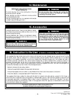
15. Accessories

The use of any other control not specifically approved for

this fan could result in fire, shock and personal injury.


WARNING

!

Do not use water when cleaning your ceiling fan.

It could damage the motor or the blades and create the

possibility of an electrical shock.


WARNING

!

IMPORTANT CARE INSTRUCTIONS

for your Ceiling Fan

Periodic  cleaning  of  your  new  ceiling  fan  is  the  only
maintenance that is needed.

When  cleaning,  use  only  a  soft  brush  or  lint  free  cloth  to
avoid scratching the finish.

Abrasive cleaning agents are not required and should be
avoided to prevent damage to finish.

14. Maintenance

16. Instruction to the User

(if device contains a digital device)

This equipment has been tested and found to comply with the limits for a class B digital device, pursuant to part 15 of the
FCC  Rules.  These  limits  are  designed  to  provide  reasonable  protection  against  harmful  interference  in  a  residential
installation.  This  equipment  generates,  uses  and  can  radiate  radio  frequency  energy  and  if  not  installed  and  used  in
accordance  with  the  instructions,  may  cause  harmful  interference  to  radio  communications.  However,  there  is  no
guarantee that interference will not occur in a particular installation. If this equipment does cause harmful interference to
radio or television reception, which can be determined by turning the equipment off and on, the user is encouraged to try
to correct the interference by one or more of the following measures:

• Reorient or relocate the receiving antenna.

• Increase the separation between the equipment and receiver.

• Connect the equipment into an outlet on a circuit different from that to which the receiver is connected.

• Consult the dealer or an experienced radio/TV technician for help.

This equipment has been certified to comply with the limits for a class B computing device, pursuant to FCC Rules. In
order  to  maintain  compliance  with  FCC  regulations,  shielded  cables  must  be  used  with  this  equipment.  Operation  with
non-approved  equipment  or  unshielded  cables  is  likely  to  result  in  interference  to  radio  and  TV  reception.  The  user  is
cautioned  that  changes  and  modifications  made  to  the  equipment  without  the  approval  of  manufacturer  could  void  the
user’s authority to operate this equipment.

This Class B digital apparatus meets all requirements of the

Canadian Interference-Causing Equipment Regulations.

25

emersonfans.com

Please contact 1-800-654-3545 for further assistance

E.T.L. Model No.: CF985

Содержание AIRA ECO CF985BS00

Страница 1: ...day Friday Part No F40BP75000000 Form No BP7500 Revision 150108 E T L Model No CF985 www emersonfans com CF985BS00 Brushed Steel CF985ORB00 Oil Rubbed Bronze Net Weight 32 6 Lbs READ AND SAVETHESE INSTRUCTIONS 1 800 654 3545 AIRA ECO 72 Damp Location Ceiling Fan Owner s Manual Model Numbers Español página 31 Français page 61 ...

Страница 2: ...cian WARNING To reduce the risk of electrical shock this fan must be installed with an isolating wall control switch WARNING To avoid fire shock or injury do not use an Emerson or any other brand of control not specifically approved for this fan WARNING This product is designed to use only those parts supplied with this product and or any accessories designated specifically for use this product by...

Страница 3: ...parts are missing call 1 800 654 3545 for replacement parts before proceeding A F G H I J K N M E D C B L PACKAGE CONTENTS 8 7 10 11 9 1 3 2 4 5 6 HARDWARE CONTENTS Part Description Quantity 1 8 32 x 8mm Washer Head Screws 41 2 1 4 20 x 1 2 Oval Head Screw 17 3 Wire Connectors 12 ga 5 4 Threaded Studs 8 32 x 1 1 4 2 5 Knurled Knobs 8 32 2 6 Lockwashers External Tooth 8 2 7 6 32 x 3 8 Truss Head Sc...

Страница 4: ...duce the risk of fire electric shock or personal injury mount fan to outlet box marked Acceptable for Fan Support of 22 7 kg 50 lbs or less and use screws supplied with outlet box Most outlet boxes commonly used for support of light fixtures are not acceptable for fan support and may need to be replaced Consult a qualified electrician if in doubt WARNING Turning off wall switch is not sufficient T...

Страница 5: ...he circuit breaker or fuse box before attempting to install the ceiling fan hanger bracket on the outlet box SETSCREW LOOSENED HANGER BALL 6 DOWNROD PIN Figure 1 3 Ceiling Fan Assembly 3 2 Remove the hanger ball by loosening the setscrew in the hanger ball until the ball falls freely down the downrod Figure 1 Remove the pin from the downrod then remove the hanger ball Retain the pin and hanger bal...

Страница 6: ...in is properly installed 6 DOWNROD RETIGHTEN SETSCREWS 2 MOTOR COUPLING 3 5 While pulling up on the 6 downrod retighten the two setscrews previously loosened in the motor coupling to secure the downrod into place Figure 4 NOTE The setscrews must be properly installed as described above or fan wobble could result 6 DOWNROD MOTOR HOUSING COUPLING COVER COUPLING COVER GROMMET Figure 5 3 6 Route the 8...

Страница 7: ...leads through the hanger ball Reinstall the hanger ball Figure 7 on the downrod as follows Position the hanger ball pin through the two holes in the downrod and align the ball so the pin is captured in the groove in the top of the hanger ball Pull the hanger ball up tight against the pin and securely tighten the setscrew in the hanger ball NOTE A loose setscrew could create fan wobble HANGER BALL ...

Страница 8: ...outlet boxes commonly used for support of light fixtures are not acceptable for fan support and may need to be replaced Consult a qualified electrician if in doubt WARNING 4 How to Hang Your Ceiling Fan FLOOR AT LEAST 7 CEILING Figure 9 OUTLET BOX SCREWS 2 HANGER BRACKET OUTLET BOX 4 1 Securely attach the hanger bracket to the outlet box using the two screws supplied with the outlet box Figure 10 ...

Страница 9: ... HANGER BRACKET HANGER BALL HANGER BALL GROOVE ANTI ROTATION TAB Figure 12 4 3 Carefully lift the partially assembled ceiling fan and seat the hanger ball downrod assembly on the hanger bracket Figure 12 Be sure the groove in the ball is engaged with the anti rotation tab on the hanger bracket Figure 12 HANGER BRACKET OUTLET BOX RETAINING STRAP SOCKET CAP SCREW HEX WRENCH Figure 11 4 2 Remove the ...

Страница 10: ... sure electricity is turned off at the main fuse box before wiring NOTE If you are not sure if the outlet box is grounded contact a licensed electrician for advice as it must be grounded for safe operation WARNING This product is designed to use only those parts supplied with this product and or any accessories designated specifically for use with this product by Emerson Electric Co Substitution o...

Страница 11: ...onnect the fan motor black wire to the supply black hot wire using wire connector supplied Figure 16 BLACK WIRES WHITE WIRES GREEN WIRES Figure 17 5 4 After connections have been made turn leads upward and carefully push leads into the outlet box with the white and green leads on one side of the outlet box and position the black leads on the other side of the outlet box Figure 17 Check to see that...

Страница 12: ...holes in the hanger bracket Figure 18 THREADED STUD 2 LOCKWASHER 2 KNURLED KNOB 2 CEILING COVER Figure 19 6 2 Lift the ceiling cover up to the threaded studs and turn until studs protrude through the holes in the ceiling cover Figure 19 Secure the ceiling cover in place by sliding lockwashers over the threaded studs and installing the two knurled knobs supplied Figure 19 Tighten the knurled knobs ...

Страница 13: ... per blade flange assembly MOTOR HUB FLANGE BLADE ASSEMBLY FLANGE NTERCONNECT NG L Figure 22 7 3 Attach the flange blade assembly to the motor hub using two 1 4 20 x 1 2 oval head screws supplied Figure 22 Attach the flange blade assemblies clockwise making sure that the interconnecting lip of the flanges mate with the next flange attachment Figure 22 Repeat this procedure for the other seven flan...

Страница 14: ... 32 x 3 8 truss head screw with lockwasher previously removed into the light fitter housing Figure 24 REINSTALL ONE 6 32 x 3 8 TRUSS HEAD SCREW WITH LOCKWASHER LIGHT FITTER HOUSING ROTATE LIGHT FITTER HOUSING CLOCKWISE TO ENGAGE THE TWO LOOSENED SCREWS Figure 24 To avoid possible fire or shock do not pinch wires between the fan motor assembly and the light fitter housing WARNING 8 1 Remove one of ...

Страница 15: ... 8 3 Connect the white wire from the fan motor assembly to the white wire of the light fitter Figure 25 Connect the black wire from the fan motor assembly to the black wire of the light fitter Figure 25 LIGHT FITTER HOUSING WHITE WIRE LIGHT FITTER HOUSING BLACK WIRE FAN MOTOR ASSEMBLY BLACK WIRE FAN MOTOR ASSEMBLY WHITE WIRE Figure 25 To avoid possible fire or shock do not pinch wires between the ...

Страница 16: ... No light Cover Plate skip this section and go to Section 9 8 6 Light Fitter Light Bulb Installation If light fitter is to be used as a down light screw in two 50 watt maximum mini candelabra base halogen bulbs supplied into the light fitter sockets Figure 28 CAUTION To avoid risk of burns or other injury assure power is off before attempting to install or replace the 50 watt max mini candelabra b...

Страница 17: ...to cool sufficiently before handling CAUTION Do not touch 50 watt max mini candelabra base halogen bulbs with bare hands Fingerprints may result in shorter bulb life Remove fingerprints with alcohol REMOVE 50 WATT max MINI CANDELABRA BASE HALOGEN BULBS 2 ROTATE GLASS BOWL COUNTER CLOCKWISE TO REMOVE FROM LIGHT FITTER GLASS BOWL LIGHT FITTER Figure 30 9 2 Place the no light cover plate into the lig...

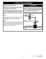
Страница 18: ...switches are factory set in the ON up position Change the switch settings as follows NOTE Do not duplicate the code of an existing control of an installed ceiling fan within 100 feet 10 3 Slide the five switch levers in the SW605 wall control to your choice of ON up or down positions Use a ball point pen or small screwdriver and slide the levers firmly up or down 10 4 The sixth switch marked ON an...

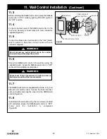
Страница 19: ...ARNING CAUTION To reduce the risk of electrical shock disconnect the electrical supply circuit before installing the fan light kit or receiver NOTE Make all wiring connections using wire connectors supplied Make sure that all connections are tight including ground and that no bare wire is visible at the wire connectors except for the ground wire 11 1 Disconnect electrical power to the branch circu...

Страница 20: ...mode until fan installation is completed 11 7 The SW605 wall control is supplied with a white ivory and almond color switch covers Choose the finish that best suits your needs and snap the cover onto the SW605 wall control Figure 34 11 8 Install decorator wall plate using the two screws provided with wall plate Leave the SW605 wall control in OFF mode until fan installation is completed Figure 34 ...

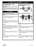
Страница 21: ...control in the wall box containing the hot wire first Connect the black wire of the SW605 wall control to the hot wire Securely connect the wires with wire connectors supplied 11 13 Connect the other black wire of the SW605 wall control to both remaining traveler wires in the wall box and secure with wire connector supplied HOT BLACK SW605 FAN LIGHT WALL CONTROL TRAVELER WIRE BLK BLK LOAD GROUND N...

Страница 22: ...ed 11 17 Connect one black wire of the SW605 wall control to the load black wire and secure with wire connector supplied 11 18 Connect one black wire of the SW605 wall control to both remaining traveler wires in the wall box and secure with wire connector supplied Figure 36 Check to see that all connections are tight and that no bare wires are visible at the wire connectors WARNING STANDARD WIRING...

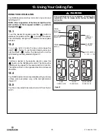
Страница 23: ...has been paired with the receiver IMPORTANT Immediately after successful pairing the ceiling fan will automatically begin high speed conditioning of the motor During conditioning the electronic motor control software is calculating speeds for the 2nd through 5th speed settings based on the blades that were installed on the fan 12 2 The fan will run for approximately 2 minutes in the upward directi...

Страница 24: ...cted Figure 37 13 3 If airflow is desired in the opposite direction press the button on the SW605 wall control The fan must be operating at any speed for the reverse button to function The blades will turn in the opposite direction and reverse the airflow 13 4 Your SW605 wall control comes complete with your choice of three wall cover plates ivory white and light almond Figure 37 13 5 Your fan is ...

Страница 25: ...e designed to provide reasonable protection against harmful interference in a residential installation This equipment generates uses and can radiate radio frequency energy and if not installed and used in accordance with the instructions may cause harmful interference to radio communications However there is no guarantee that interference will not occur in a particular installation If this equipme...

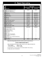
Страница 26: ...26 E T L Model No CF985 17 Repair Parts PARTS BAG 16 17 18 13 21 19 22 23 20 17 18 5 6 7 8 19 9 20 12 11 10 3 2 13 1 14 15 15 14 22 22 4 ...

Страница 27: ...ht Fitter Housing 764673 BS 764673 ORB 6 Light Fitter 764683 BS 764683 ORB 7 Glass Bowl 764676 OM 764676 OM 8 Removable No Light Cover Plate 764677 BS 764677 ORB 9 Blade Flange Plate Set of 8 764667 BS 764667 ORB 10 Fan Blade Set of 8 764671 WA 764671 WA 11 Blade Flange Set of 8 764669 BS 764669 ORB 12 SW605 Wall Control Hardware 763980 1 763980 1 Parts Bag Containing 764678 CRM 764678 BLX 13 Thre...

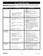
Страница 28: ...rnative control method 5 Screws holding blades to flanges 5 Tighten screws securely are loose 3 Fan wobbles 1 Setscrews in motor coupling are loose 1 Tighten both setscrews securely in the motor excessively coupling 2 Setscrew in hanger ball downrod 2 Tighten the setscrew in the hanger ball assembly is loose downrod assembly 3 Screws securing fan blade flanges to 3 Check to be sure screws which at...

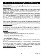
Страница 29: ...is limited warranty You can return your Emerson Ceiling Fan to your place of purchase or you can call Emerson Customer Service at 1 800 237 6511 to obtain a return authorization and service identification tag In order for us to confirm that your Emerson Ceiling Fan is still under warranty please retain your receipt or other proof of purchase and have that information readily available when returni...

Страница 30: ...Service 8 a m 6 p m Eastern Monday Friday 1 800 654 3545 www emersonfans com Retain this manual for future use Air Comfort Products DIVISION OF EmErSON ElEctrIc cO 8100 W Florissant St louis mO 63136 Part No F40BP75000000 Form No BP7500 Revision 150108 E T L Model No CF985 Printed in China 01 15 ...

Отзывы: