


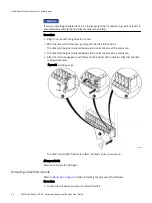
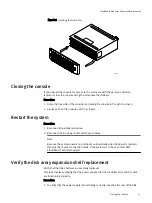

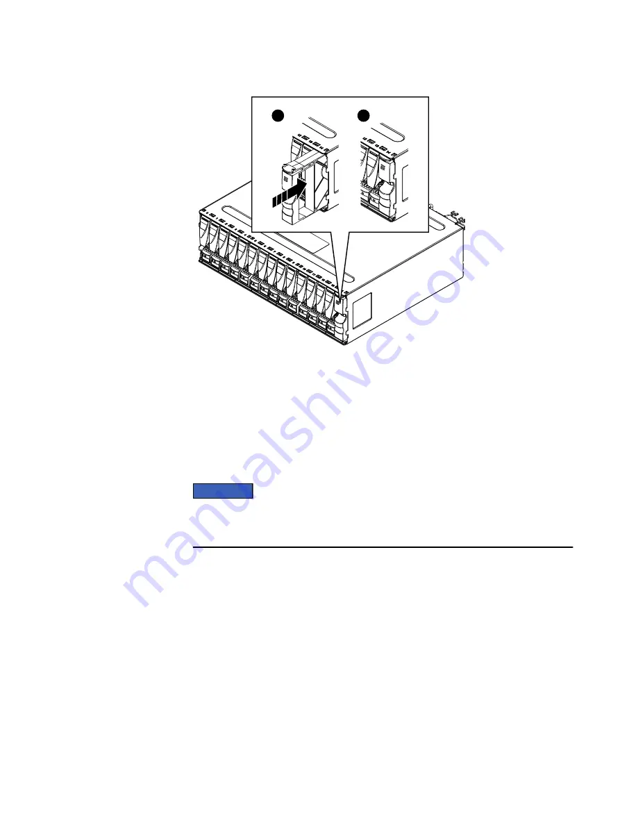
Figure 27 Installing a disk filler module
2
1
CL5284
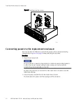
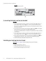
Connecting powers to the replacement enclosure
Use the procedure that follows to connect the AC power cord to each power/cooling
module. Refer to
while performing the procedure.
Procedure
1. Plug in the AC power cord.
NOTICE
Do not connection a power/cooling module in an optional power/cooling module to
an SPS. Only connect a power/cooling module in enclosure 0 on bus 0, which
contains the system (vault) disks, to the SPS.
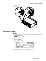
As soon as the enclosure is connected to a live power source, it powers up and its
lights begin blinking.
2. Secure the power cord with the retention bail at the connector.
The bail prevents the power cord from pulling out of the connector.
CloudBoost Disk Array Expansion Replacement
50
EMC CloudBoost 100
2.0
Hardware Component Replacement Guide
Содержание CloudBoost 100
Страница 1: ...EMC CloudBoost 100 Version 2 0 Hardware Component Replacement Guide P N 302 002 471 REV 02 ...
Страница 6: ...FIGURES 6 EMC CloudBoost 100 2 0 Hardware Component Replacement Guide ...
Страница 8: ...TABLES 8 EMC CloudBoost 100 2 0 Hardware Component Replacement Guide ...
Страница 14: ...CloudBoost 100 Overview 14 EMC CloudBoost 100 2 0 Hardware Component Replacement Guide ...
Страница 20: ...Disk Drive Replacement 20 EMC CloudBoost 100 2 0 Hardware Component Replacement Guide ...


