Veronte PCS
3.3 How to operate
Veronte PCS is a pre-configured device which requires some particular connections. Below there are some
configurations for the setup of the PCS system. Particularly, establishing connection between the Control Station and
PCS (via USB or Wi-Fi/Ethernet), Joystick and Tracking Antennas Connection and a Troubleshooting section.
Important:
Ports RS232 and RS485 have some particularities. Refer to chapter Matters Need Attention in Installation
section form more information.
3.3.1 Computer Connection
USB
• Connect your PCS to your Control Station via USB.
• Open Pipe and go to Preferences – Connections – Serial COM – Add – Serial COM which matches the Veronte.
Wi-Fi / Ethernet
Warning:
If the radio frequency in use is 2.4GHz, it is recommended to use the 5 GHz signal for PCS
communication, disabling 2.4GHz if interferences are noticed.
• First of all, a connection between the Control Station (Veronte MCS, Computer, etc) and the Veronte PCS is
needed. For that the two available options are Wi-Fi or Ethernet. If connecting through Ethernet, step 2 does not
apply.
• If connecting through Wi-Fi, search for the PCS according to the indicated network name from the identification
badge (name will be like PCSXXXXX-XXG) and connect to that network (use the password provided in the
badge as well).
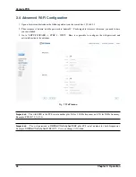
• Password can be changed in accordance to 6. Anex A. Advanced Wi-Fi configuration.
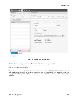
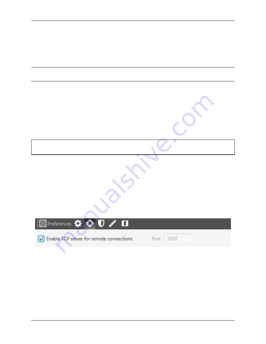
Once the connection is done, enter in Pipe, Preferences – Connections and configure Port information (set it to 3000)
and check Enable TCP box. Find the configuration in the following picture.
Fig. 1:
How to operate - TCP and port information
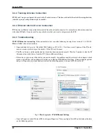
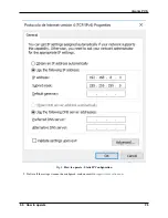
Next step is to set an Ethernet connection. Fill with the following information:
• IP:
239.0.0.1
.
• Port:
12345
• Network interface: select your ethernet board.
22
Chapter 3. Operation
Содержание Veronte PCS
Страница 1: ...Veronte PCS Embention Apr 21 2022 ...
Страница 2: ......
Страница 4: ...ii ...
Страница 8: ...Veronte PCS Fig 2 System Dimensions 4 Chapter 1 Technical ...
Страница 10: ...Veronte PCS 1 6 Interfaces Fig 4 PCS Interfaces Parts identification 6 Chapter 1 Technical ...
Страница 11: ...Veronte PCS Fig 5 PCS Interfaces Parts identification 1 6 Interfaces 7 ...
Страница 14: ...Veronte PCS 10 Chapter 1 Technical ...
Страница 24: ...Veronte PCS 20 Chapter 2 Installation ...
Страница 36: ...Veronte PCS Fig 4 Basic Features Veronte PCS 32 Chapter 4 Maintenance ...


