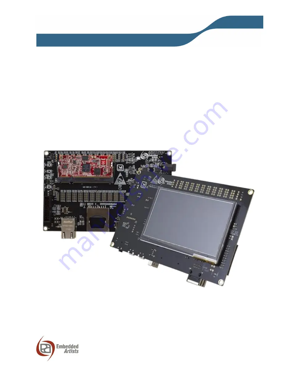
iMX RT1052
Developer’s Kit
- User’s Guide
Copyright 2018 © Embedded Artists AB
EA2-USG-1208 Rev A
iMX RT1052 Developer’s Kit
User’s Guide
Get Up-and-Running Quickly and Start Developing Your Application On Day 1!
Страница 1: ... RT1052 Developer s Kit User s Guide Copyright 2018 Embedded Artists AB EA2 USG 1208 Rev A iMX RT1052 Developer s Kit User s Guide Get Up and Running Quickly and Start Developing Your Application On Day 1 ...
Страница 2: ...ission of Embedded Artists AB Disclaimer Embedded Artists AB makes no representation or warranties with respect to the contents hereof and specifically disclaim any implied warranties or merchantability or fitness for any particular purpose Information in this publication is subject to change without notice and does not represent a commitment on the part of Embedded Artists AB Feedback We apprecia...
Страница 3: ...14 4 iMX OEM Carrier Board Design 15 4 1 Modifications to iMX OEM Carrier Board 15 4 2 SP2a Power Supplies 16 4 3 SP2b Current Measurement 18 4 4 SP2c VBAT Powering 19 4 5 SP3 SP4 OEM Board Connector SODIMM and Access Pads 20 4 6 SP5 Push buttons and LEDs 21 4 7 SP6 Debug Interfaces 23 4 8 SP7 USB Interfaces 25 4 9 SP8 CAN 26 4 10 SP9 SD Memory Card Interface 27 4 11 SP10 LCD Interface 27 4 12 SP1...
Страница 4: ...ser s Guide Page 4 Copyright 2018 Embedded Artists AB 5 3 Contact with OEM Board MCU 36 5 4 Using the Demo Application to Verify Correct Operation 36 6 Different Board Versions 37 7 Disclaimers 38 7 1 Definition of Document Status 39 ...
Страница 5: ...Revision Date Description PA2 2017 12 19 First released version PA3 2018 01 01 Moved program development information to separate document PA4 2018 02 05 Added information about SWO trace PA5 2018 02 12 Minor corrections on cross reference PA6 2018 04 17 Updated information on i MX RT1052 silicon revision A0 and A1 ...
Страница 6: ...lication that can also be used to verify correct operation of the hardware Chapter 4 presents the hardware design of the iMX OEM Carrier Board Chapter 5 contains some troubleshooting information To get started with program development and program download flashing see document iMX RT1052 Developer s Kit Program Development Guide 2 1 iMX RT1052 Developer s Kit Content One iMX RT1052 COM board mount...
Страница 7: ... press will shut down the main 3 3V supply 5 ISP Enable push button pressing this button while the board power up will place the i MX RT1052 is ISP mode typically used for programming the iMX RT1052 OEM board flash memory 6 Alternative power supply input this is an alternative power supply input 5V 1A DC via a 2 1mm power jack The center position is the positive terminal Figure 10 in chapter 4 giv...
Страница 8: ...is described in more detail in section 3 Meanwhile the PC will typically install drivers automatically for the UART to USB bridge that creates a Virtual COM port if they are not already installed If you have problems the drivers can be downloaded from the links below http www ftdichip com Drivers VCP htm http www ftdichip com Support Documents InstallGuides htm When the driver has been installed a...
Страница 9: ...sub sections 2 3 1 Tera Term Terminal Emulation Application We recommend that you use Tera Term which can be downloaded and installed from either of the links below https ttssh2 osdn jp index html en http sourceforge jp projects ttssh2 releases Launch Tera Term The first time it launches it will show you the following dialog Select the serial option Assuming the USB cable is connected to the iMX O...
Страница 10: ... from the link below http www chiark greenend org uk sgtatham putty download html Launch PuTTY by either double clicking on the exe file you downloaded or from the Start menu depending on the type of download you selected In the window that launches select the Serial radio button and enter the COM port number that you determined earlier Also enter the baud rate in this case 115200 Figure 7 PuTTY N...
Страница 11: ...l powering connected to the board at the same time but only one of them will be used at any time Powering selector J29 selects either 5V DC powering via J1 or USB powering via J22 See Figure 8 below where to locate J29 Figure 8 Location of Powering Selector J29 2 5 ESD Precaution Please note that the iMX RT1052 OEM Board and iMX OEM Carrier Board come without any case box and all components are ex...
Страница 12: ...in the SODIMM connector of the iMX OEM Carrier Board To install the OEM Board align it to the socket 1 Push the board gently and with even force between the board edges fully into the socket 2 Then push the board down in a rotating move 3 until it snaps into place 4 The OEM Board shall lie flat and parallel to the base board To remove the OEM Board spread the two arms of the SO DIMM socket apart s...
Страница 13: ...n connectors may alter EMC emission It is the user s responsibility to make sure EMC emission limits are not exceeded when connecting other devices to the general expansion connectors of the iMX RT1052 Developers Kit Due to the nature of the iMX RT1052 Developers Kit an evaluation board not for integration into an end product fast transient immunity tests and conducted radio frequency immunity tes...
Страница 14: ... a touch event is detected Detected coordinates are also printed in the console An audible tone is sent to the headphone interface It is possible to Ping the Ethernet interface The IP address is hard coded to 192 168 6 231 Received ping requests from a pc are printed on the console After 5 received pings it stops writing received pings USB Host via the USB Host connector J13 It is possible to inse...
Страница 15: ...age x The picture below gives an overview of the iMX OEM Carrier Board design Figure 10 iMX OEM Carrier Board Overview 4 1 Modifications to iMX OEM Carrier Board The iMX OEM Carrier Board has been designed to be flexible Most options can be controlled via jumpers but some options might need soldering Note that modifications to the board are done at own risk and void all warranties OEM Board Connec...
Страница 16: ...A cable when connected to J22 position 1 in Figure 1 This setup will work in most cases However note that not all PC laptops can provide the needed current A powered USB hub or an external power supply can be used in this case It is possible to have both the USB cable and external powering connected to the board at the same time but only one of them will be used at any time Powering selector J29 s...
Страница 17: ...e iMX OEM Carrier board supports both 2 9 and 3 3V on VIN_ALWAYSON When R25 2 2Mohm is mounted the voltage is 2 9V and when R25 is removed the voltage is 3 3V The picture below illustrates the location of relevant jumpers and LEDs Figure 12 Location of Power Supply Connectors and Jumpers Powering Selector J29 Left 1 2 Power via 5V DC J1 Right 2 3 Power via USB J22 default Power Supply Input J1 2 1...
Страница 18: ...ion Figure 13 Location of Current Measurement Connectors J3 and J4 Note that the main 3 3V supply powers both the iMX RT1052 OEM board and peripherals on the iMX OEM Carrier board like LCD SD interface Audio codec CAN interface LEDs etc For better discrimination and resolution of current measurement it is possible to measure currents on the iMX RT1052 OEM board also The following detailed measurem...
Страница 19: ...e VBAT input connector is J2 and where the current can be measured over a 1 kohm resistor J26 The arrow indicates the current flow direction Figure 15 Location of VBAT Connector and VBAT Current Measurement Pads VBAT Current Measurement J26 Measure current over a 1kohm resistor VBAT Input J2 GND top VBAT bottom J1 DCDC_IN current over 20 milliohm J2 VDD_SOC_ON current over 20 milliohm J3 VDD_HIGH_...
Страница 20: ... TP7 TP35 TP199 TP17 TP31 TP21 TP29 TP23 TP120 TP25 TP27 TP177 TP179 TP19 TP181 TP185 TP187 TP189 TP183 TP6 TP51 TP61 TP53 TP63 TP55 TP67 TP57 TP59 TP81 TP95 TP83 TP91 TP85 TP18 TP87 TP89 TP111 TP125 TP113 TP123 TP115 TP68 TP117 TP119 TP143 TP159 TP145 TP155 TP147 TP153 TP149 TP151 TP37 TP49 TP39 TP47 TP41 TP121 TP43 TP45 TP65 TP79 TP69 TP77 TP71 TP92 TP73 TP75 TP97 TP109 TP99 TP107 TP101 TP157 TP...
Страница 21: ...tion Jumper in 1 2 position on JP8 controls signal POR_B which results in a so called warm reset of the i MX RT1052 MCU Figure 17 Location of Push buttons There is also jumper to allow a specific signal GPIO_B1_13 to control the watchdog input signal WDOG_B This jumper is inserted by default Figure 18 Location of Watchdog Control Jumper J9 Wakeup push button SW4 Reset push button SW3 ON OFF push b...
Страница 22: ...AB There are two LEDs that are not connected by default to specific signals Via jumpers to J8 any signal that is available on the access pads described in section 4 5 can be used to control the LEDs Figure 19 Location of User LEDs User LEDs J8 left position LED6 J8 right position LED7 ...
Страница 23: ...AG SWD interface on the i MX RT1052 JP5 shall not be shorted inserted Figure 20 Debug Interfaces Note that due to the errata on i MX RT1052 rev A0 silicon the debug probe I O voltage MUST follow the i MX RT1052 I O voltage The debug adapter must not drive any output higher than the Vcc Vref voltage and if that voltage is zero then the debug adapter must not drive any output signal Vcc Vref is pin ...
Страница 24: ... add the call to IOMUXC_SetPinMux and IOMUXC_SetPinConfig in function BOARD_InitPins as outlined below define IOMUXC_GPIO_B0_13_SWO 0x401F8170U 0x2U 0 0 0x401F8360U void BOARD_InitPins void GPIO_B0_13 is configured as SWO ALT2 Sw Input On Field Input Path is determined by functionality IOMUXC_SetPinMux IOMUXC_GPIO_B0_13_SWO 0U GPIO_B0_13 PAD functional properties Slew Rate Field Fast Slew Rate Dri...
Страница 25: ...this interface has VBUS control via the ID pin This USB interface is connected to i MX RT1052 USB interface 1 o If no cable is inserted or when a cable with ID pin floating is inserted VBUS will not be powered on the J12 connector o If a cable with the ID pin grounded is inserted VBUS will be turned on i e powered with 5V This is the typical situation when connecting a mini AB to USB A USB cable i...
Страница 26: ...ne CAN interface on the board It is connected to FLEXCAN2 of the i MX RT1052 The interface has on board ESD protection via U9 See picture below for locating relevant components Figure 22 CAN Interface CAN part of Connector J14 From top to bottom CANH CANL GND Termination Resistors R71 R70 CAN standby ctrl JP2 ...
Страница 27: ...PIO_SD_B0_01 mount R150 to access the signal via TP69 GPIO_SD_B0_03 mount R151 to access the signal via TP73 GPIO_SD_B0_05 mount R152 to access the signal via TP75 R150 R152 can be found on the bottom side just under the middle of the SODIMM connector and under the LCD R150 R152 are 0 ohm 0402 resistors 4 11 SP10 LCD Interface There is a 4 3 inch LCD with capacitive touch panel and 480x272 pixel r...
Страница 28: ...one for interrupt There is a backlight current generator that is set to 40mA It can optionally be controlled with a PWM signal to dim the backlight 4 12 SP11 Ethernet Interface The board has an Ethernet interface J20 which is a RJ45 connector with integrated magnetics See picture below for where to find the location of J20 Figure 24 Location of Ethernet Interface J20 RJ45 with Magnetics J20 ...
Страница 29: ...rt also offers the possibility to power the board It is possible to disconnect the UART to USB bridge chip from UART channel 1 via JP3 for example if the UART needs to be connected to another device There are two LEDs transmit from the board LED11 and receive to the board LED10 that signal communication activity See picture below for locating relevant components Figure 25 UART to USB Bridge USB mi...
Страница 30: ...put via JP4 The audio interface is via a 3 5 mm audio jack J23 with four conductors TRRS supporting stereo sound and a microphone input There are two types of signal allocation on the 3 5mm headphone connector Location of ground and the microphone input signal differs JP7 makes it possible to msockest See picture below for locating relevant components Figure 26 I2S Audio Codec Interface Audio Jack...
Страница 31: ...2018 Embedded Artists AB 4 15 Default Jumpers Positions Figure 27 illustrates the default jumper positions as mounted when the board is delivered from Embedded Artists Default jumpers are marked with red color Figure 27 iMX OEM Base Board Default Jumper Positions ...
Страница 32: ... JTAG_TDO GPIO_AD_B0_10 Connects to Arm Cortex debug connectors GPIO0 LCDIF_PWREN GPIO_AD_B0_04 No special usage on iMX OEM Carrier Board GPIO2 LCDIF_CLK GPIO_B0_00 Parallel RGB LCD interface LPC Pixel Clock GPIO3 LCDIF_VSYNC GPIO_B0_03 Parallel RGB LCD interface LPC VSYNC GPIO4 LCDIF_ENABLE GPIO_B0_01 Parallel RGB LCD interface LPC Data Enable GPIO5 LCDIF_HSYNC GPIO_B0_02 Parallel RGB LCD interfa...
Страница 33: ... connects to audio codec and capacitive touch panel controller GPIO_SD_B0_01 SD1_CLK GPIO_SD_B0_01 Connects to SD interface CLK GPIO_SD_B0_00 SD1_CMD GPIO_SD_B0_00 Connects to SD interface CMD GPIO_AD_B0_05 BOOT_MODE1 FLASH_RST GPIO_AD_B0_05 Connects to SD interface power control GPIO_SD_B0_02 SD1_D0 GPIO_SD_B0_02 Connects to SD interface Data0 GPIO_SD_B0_03 SD1_D1 GPIO_SD_B0_03 Connects to SD int...
Страница 34: ...nects to audio codec RX_DATA POR_B POR_B No special usage on iMX OEM Carrier Board Can optionally be controlled by SW3 if JP8 is in 2 3 pos ONOFF ONOFF Connects to push button SW2 OTG1_CHD OTG1_CHD No special usage on iMX OEM Carrier Board WAKEUP WAKEUP Connects to push button SW4 GPIO_AD_B1_09 SAI1_MCLK GPIO_AD_B1_09 Connects to audio codec MCLK PMIC_ON_REQ PMIC_ON_REQ Reset generator No special ...
Страница 35: ... also starts up before the main 3 3V power supply Also note that due to the errata on i MX RT1052 rev A0 silicon the debug probe I O voltage MUST follow the i MX RT1052 I O voltage The debug adapter must not drive any output higher than the Vcc Vref voltage and if that voltage is zero then the debug adapter must not drive any output signal Vcc Vref is pin 1 on both J10 and J11 Make sure the debug ...
Страница 36: ...boards delivered before April 2018 It is 3 3V in boards delivered after April 2018 Verify that the voltage measured over J4 is less than 25 mV 5 Verify that you have 3 3V 0 15V on any of the pins of J3 This is the main voltage supply Also verify that LED3 is on Verify that the voltage measured over J3 is less than 50 mV 6 Press the reset push button SW3 Verify that LED3 is off while pressing SW3 7...
Страница 37: ...sing versions numbers Therefore this chapter contains information about different board versions and i MX RT1052 silicon versions iMX RT1052 OEM Board version i MX RT1052 Silicon Version i MX RT1052 Top Marking iMX RT1052 OEM Board rev PA4 A0 PIMXRT1052DVL6A comm PIMXRT1052CVL5A ind iMX RT1052 OEM Board rev A1 and A2 Rev A1 is a board with SDRAM Rev A2 is a board without SDRAM A1 MIMXRT1052DVL6B c...
Страница 38: ...ould be followed Embedded Artists does not accept any liability and no warranty is given for any unexpected software behavior due to deficient components Customer is required to take note of manufacturer s specification of used components for example MCU SDRAM and FLASH Such specifications if applicable contains additional information that must be taken note of for the safe and reliable operation ...
Страница 39: ...a draft version only The content is still under internal review and subject to formal approval which may result in modifications or additions Embedded Artists does not give any representations or warranties as to the accuracy or completeness of information included herein and shall have no liability for the consequences of use of such information The document is in this state until the product has...
Страница 40: ...Mouser Electronics Authorized Distributor Click to View Pricing Inventory Delivery Lifecycle Information Embedded Artists EAK00296 ...