EMB Wallenstein CR Series Скачать руководство пользователя страница 26

26

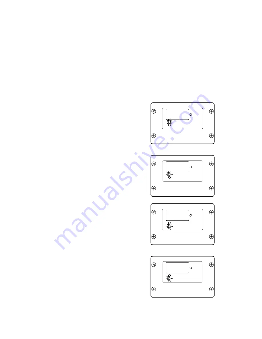
1.  Programming Upper RPM Limit (Ceiling):


•  Press mode button twice.  Digital readout will 

display current upper limit setting.  This repre-

sents the RPM at which the Rapid Recovery 

Auto Reverse will re-start the feed rolls after 

a suspension.

• 

Oil Use indicator will flash.  Increase or de

-

crease setting using program buttons (factory 

setting is 1375 RPM)

2.  Programming Upper Flow Percentage:

•  Press mode button once more.  Digital read-

out will display current upper flow setting.  This 

represents the percent of hydraulic flow that 

will be sent to the feed rolls (Feed speed.).

• 

Oil Use indicator will flash.  Increase or de

-

crease setting using program buttons, do not 

set above 80 % (factory setting is  75%)

3.  Programming Lower RPM Limit (Floor) :

•  Press mode button once more.  Digital rea-

dout will display current lower limit setting.  

This represents the rotor RPM at which the 

Rapid Recovery Auto Reverse will reverse 

and suspend the feed rolls. 

• 

Machine hours indicator will flash.  Increase 

or decrease setting using program buttons. 

(factory setting is 900 RPM)

4.  Programming Lower Flow Percentage:


•  Press mode button once more.  Digital read-

out will display current lower flow setting.  This 

represents the percent of hydraulic flow that 

will be sent to the feed rolls (Feed speed.).

• 

Machine hours indicator will flash.  Increase 

or decrease setting using program buttons, 

do not set below 25% (factory setting is 35%)

8888

ROTOR

R. P. M.

OIL   USE    HOURS

MACHINE HOURS

EMB   MFG   INC.

8888

ROTOR

R. P. M.

OIL   USE    HOURS

MACHINE HOURS

EMB   MFG   INC.

8888

ROTOR

R. P. M.

OIL   USE    HOURS

MACHINE HOURS

EMB   MFG   INC.

8888

ROTOR

R. P. M.

OIL   USE    HOURS

MACHINE HOURS

EMB   MFG   INC.

1

375

88

75

0

900

88

35

4.4.2 INTELLIFEED PROGRAMMING:

The factory settings provide good overall performance for the CR70, however you may under certain 

circumstances, choose to customize performance. (controller is accessible through the battery access 

door.) Programmable features of Intellifeed include: the upper and lower RPM limits (rotor speed) and 

the upper and lower flow percentage (roller speed).

How best to adjust the programming will come from experience and common sense, if in doubt set to 

factory setting for optimum performance.
Here are some helpful hints:
• 

For heavier brush, decrease the upper flow percentage for slower feed speed.

• 

For lighter brush, increase the upper flow percentage for faster feed speed.

• 

If the chipper is stalling before the feed rolls stop, increase the rotor floor setting.

• 

If you prefer more aggressive feeding with faster feed and more stops, increase the lower flow 

percentage.

Содержание Wallenstein CR Series

Страница 1: ...IPPER OPERATOR S MANUAL PRINTED IN CANADA REV 210815 PART NUMBER Z97071 Before putting the CR70 into service Do not attempt to start or operate the chipper without receiving full safety training and instruction in its features operation and maintenance See page 5 for Pre Delivery Procedure Keep this manual with the CR70 at all times CR70 S N 2E9US1112FS010013 2E9US1119H010026 ...

Страница 2: ...W 2 23 4 3 CONTROLS 24 4 3 1 ENGINE KOHLER CH980 38HP 24 4 4 INTELLIFEED FEATURES AND PROGRAMMING 25 4 4 1 INTELLIFEED FEATURES 25 4 4 2 INTELLIFEED PROGRAMMING 26 4 5 DISCHARGE CHUTE 27 4 6 HOOD DEFLECTOR 27 4 7 EASY START 27 4 8 ROLLER FEED CONTROL BAR 28 5 OPERATION PROCEDURE 29 5 1 PREPARE 29 5 2 MACHINE BREAK IN 30 5 3 PREOPERATION CHECKLIST 30 5 4 TRAILER TOW VEHICLE 31 5 4 1 BALL COUPLING 3...

Страница 3: ...Y 49 8 2 4 HYDRAULIC OIL FILL 49 8 2 5 HYDRAULIC OIL DRAIN 50 8 2 6 HYDRAULIC OIL FILTER 51 8 2 7 SERVICING THE BATTERY 52 8 2 8 DRIVE BELT REPLACEMENT 53 8 2 9 BELT TENSION 54 8 2 10 SHEAVE ALIGNMENT 55 8 2 11 ROTOR BLADES 56 8 2 12 LEDGER BLADES 57 8 2 13 TWIG BREAKER 58 9 TROUBLE SHOOTING 59 10 SPECIFICATIONS 63 10 1 MECHANICAL 63 10 2 BOLT TORQUE 64 10 3 HYDRAULIC FITTING TORQUE 65 10 4 WHEEL ...

Страница 4: ...covered by the warranty period specified by that manufacturer Engine warranty must be registered at the engine manufactures website For service contact your local engine dealer Under no circumstances will the manufacturer be liable for any consequential damage or expense of any kind including loss of profits The manufacturer is under no circumstances liable for tow vehicle of any kind The manufact...

Страница 5: ...eely Guards and Shields Installed and Secured Check Function of Brake and Signal Lighting Safety Chain on Hitch Retainer Installed Through Ball Hitch Tire Pressure Wheel Lugs at Proper Torque Review Operating and Safety Instructions _________________________________________ Owner Owner Representative _________________________________________ Address _________________________________________ ______...

Страница 6: ...RITE DES VEHICLES AUTOMOBILES DU CANADA EN VIGUEUR A LA DATE DE SA FABRICATION LABELLING INFORMATION As you begin to get familiar with your Wallenstein product you will notice that there are numerous labels located on the machine Here is a brief explanation of what they are for and how to read them There are three different types of labelling safety informative and product labels Safety Labels are...

Страница 7: ... consistent sized chips exiting the machine The rotor paddles move the processed material from the rotor housing out to the adjustable discharge hood where the material is directed to where you want it A powerful engine is mounted on the frame to drive the rotor Power is transmitted through a fluid coupling that acts as a clutch on the engine output shaft to a V belt drive system on the rotor An h...

Страница 8: ... 914 1842 or Fax 519 699 4146 DANGER Indicates an imminently hazardous situation that if not avoided will result in death or serious injury This signal word is to be limited to the most extreme situations typically for machine components which for func tional purposes cannot be guarded WARNING Indicates a potentially hazardous situation that if not avoided could result in death or serious injury a...

Страница 9: ...ng of the machine DO NOT modify the equipment in any way Unauthorized modification may impair the function and or safety and could affect the life of the equipment DO NOT allow riders DO NOT risk injury or death by ignoring good safety practices DO review safety related items annually with all personnel who will operating or maintaining the Trailer Wood Chipper DO have a first aid kit available fo...

Страница 10: ...ngerous to children and persons unfamiliar with its operation The operator should be a responsible properly trained and physically able person familiar with machinery and trained in this equipment s operations If the elderly are assisting with work their physical limitations need to be recognized and accommodated 6 Never exceed the limits of a piece of machin ery If its ability to do a job or to d...

Страница 11: ...elf or is loaned or rented it is the machine owner s responsibility to make certain that the operator prior to using Reads and understands the operator s manuals Is instructed in safe and proper use of the equipment Understands and knows how to perform the safe condition procedure shut off the engine ensure all components have stopped moving remove and pocket the ignition key disconnect the batter...

Страница 12: ...ssages found on the safety signs on the engine and machine 2 Personal protection equipment including hard hat safety glasses safety shoes gloves hearing protection safety vest are recommended during assembly instal lation operation adjustment maintaining repairing removal cleaning or moving the chipper Do not allow long hair loose fitting clothing or jewellery to be around equipment 3 PROLONGED EX...

Страница 13: ...lways use proper tools that are in good con dition Make sure you understand how to use them before performing any service work 2 5 MAINTENANCE SAFETY 1 Good maintenance is your responsibility Poor maintenance is an invitation to trouble 2 Follow good shop practices Keep service area clean and dry Be sure electrical outlets and tools are properly grounded Use adequate light for the job at hand 3 Ma...

Страница 14: ...ng or jewellery to be around moving parts 6 Keep hydraulic lines and fittings tight in good condition and free of leaks 7 Inspect electrical harness sensors and con troller to ensure they are in good condition before operating to maintain control 8 Never place any part of your body where it would be in danger if movement should occur during assembly installation operation main tenance repairing un...

Страница 15: ...er 16 Check that all the lights reflectors and other lighting requirements are installed and in good working condition 17 Check that trailer brakes are functioning properly 18 Never allow riders on the machine 19 Be a safe and courteous driver Always yield to oncoming traffic in all situations including narrow bridges intersections etc 20 Watch for traffic when near or crossing road ways 21 Do not...

Страница 16: ...O NOT operate engine with an accumula tion of grass leaves dirt or other combustible materials in the muffler area 12 DO NOT touch hot muffler cylinder or fins because contact may cause burns 13 DO NOT run engine without air cleaner or air cleaner cover removed 14 DO NOT use this engine on any forest covered brush covered or grass covered unimproved land unless a spark arrester is installed on the...

Страница 17: ...from the feed roller 3 Never climb onto the feed table or hopper when the chipper is operating or running 4 Never allow anyone to sit on the feed table 5 When feeding material into the feed roller wear eye face and hearing protection 2 14 BATTERY SAFETY 1 Wear gloves and safety glasses or face shield when working on or near batteries 2 Use a battery carrier to lift the battery or place hands at op...

Страница 18: ... anyone else to use this chipper until such information has been reviewed Annually review this information before the season start up Make these periodic reviews of SAFETY and OPERATION a standard practice for all of your equipment We feel that an untrained operator is unqualified to use this machine A sign off sheet is provided for your record keeping to show that all personnel who will be workin...

Страница 19: ...th care Z94119 Caution read and understand ALL safety and operating instructions in the manual read and understand ALL safety labels located on the machine The most important safety device on this equipment is an informed SAFE operator 3 2 SAFETY SIGN EXPLANATIONS 3 1 HOW TO INSTALL SAFETY SIGNS Be sure that the installation area is clean and dry Be sure temperature is above 50 F 10 C Determine ex...

Страница 20: ...4119 Z94115 The types of safety signs and locations on the equipment are shown in the illustrations that follow Good safety requires that you familiarize yourself with the various safety signs the type of warning and the area or particular function related to that area that requires your SAFETY AWARENESS Think SAFETY Work SAFELY Z94120 Z94117 Z94124 Z94124 ...

Страница 21: ...re recommended during assembly installation operation adjustment maintaining or repairing Do not allow long hair loose fitting clothing or jewellery to be around moving parts Turn machine off stop and disable en gine remove ignition key and place in your pocket set park brake and wait for all mov ing parts to stop before servicing adjusting repairing or unplugging Do not run machine inside a close...

Страница 22: ...omponent descrip tions here are used throughout the manual to explain function and safety For a detailed parts breakdown see your dealer or visit the Wallenstein website to download the CR70 Parts Manual Upper Rotor Housing Discharge Chute Fluid Coupling Ledger Blade Twig Breaker Feed Roller Control Bar Feed Hopper Feed Table Rotor Blade Double B V Belt x 70 4 2 1 COMPONENT VIEW 1 Hood Deflector L...

Страница 23: ... Switch Grip Handle Chute Latch Handle Tank Compartment View Torflex 7000 lb Axle Brake and Hub Ass y 4 2 2 COMPONENT VIEW 2 M Fuel Tank Hydraulic Tank Tool Tray Rotor Safety Interlock Lever Rotor Safety Interlock Connector Upper Housing Lock Pin Interlock Lever Lock Pin Tank Door Tongue Jack ...

Страница 24: ...ll the features available on the CR70 and apply them as conditions demand OFF Turn key fully counter clockwise to stop the electrical system power and turn the engine off RUN ON Turn clockwise to the centre detent for the run position This is the posi tion where the engine will continue to run START Turn fully clockwise to the last spring loaded detent position to engage the starter solenoid and s...

Страница 25: ...s is the default display when to rotor is not turning When the ignition switch is turned to run the oil use indicator lights up the display indicates the number of hours the oil has been in use oil use hours can be reset by depress ing the function control for 10 seconds Machine Hours with the rotor at rest depressing the mode button once activates the machine hours indicator the display shows tot...

Страница 26: ...his represents the percent of hydraulic flow that will be sent to the feed rolls Feed speed Machine hours indicator will flash Increase or decrease setting using program buttons do not set below 25 factory setting is 35 8888 ROTOR R P M OIL USE HOURS MACHINE HOURS EMB MFG INC 8888 ROTOR R P M OIL USE HOURS MACHINE HOURS EMB MFG INC 8888 ROTOR R P M OIL USE HOURS MACHINE HOURS EMB MFG INC 8888 ROTO...

Страница 27: ...ion activates Two nut handles on each side of the feed roller control the spring tension adjustment 1 Turn the bottom nut handle counter clockwise to unjam the nut handles 2 Turn the top nut handle clockwise to increase tension or counter clockwise to decrease tension adjust each side of feed rollers evenly 3 Jam the nut handles to lock them in place Grip Handle Latch Handle Nut Handles Slots Defl...

Страница 28: ... the next detent position and the feed rollers begin to turn forward feed This is the normal operating position for the control bar and will stay in position until moved 3 Push the bar to its next position and the feed rollers will reverse When the control bar is released it will automatically return to the forward feed position The control bar can be moved freely between forward and reverse witho...

Страница 29: ... operating this machine while taking prescription medications Never allow children or unauthorized people to operate or be around this machine Do not reach into rotor or feed hopper open ings when the engine is running Install and secure access covers before starting engine Do not move or transport chipper when the rotor is turning Keep hydraulic lines and fittings tight in good condition and free...

Страница 30: ...each operator reads and understands the use procedures and all related safety precautions outlined in this section A PreOperation checklist is provided for the opera tor It is important for both the personal safety and maintaining good mechanical condition that this checklist is followed Before operating the Wood Chipper and each time thereafter the following areas should be checked off Pre Operat...

Страница 31: ...he hitch and ball are aligned 5 Attach the ball hitch a Place the coupler over the ball on the hitch b Flip the latch to lock the coupler around the ball and install c Install the snapper pin to secure the latch d Wind the jack up Snapper Pin Harness Cable Safety Chain Wind up Jack Leg 6 Attach the safety chain securely to the tow vehicle to prevent unexpected separation Cross the chains when atta...

Страница 32: ...rs especially small children are clear of the working area 2 Make sure there is enough room and clear ance to safely back up to the machine 3 Use the trailer jack to raise the pintle to the height of the pintle hook 4 Slowly back the tow vehicle until the pintle hook and pintle ring are aligned 6 Close the latch on the pintle hook and install latch pin 7 Pull the jack pin crank the jack up 8 Rever...

Страница 33: ... the machine so the pre vailing wind breeze blows the ex haust gases fumes away from the operator s station 4 Release the two spring loaded latch pins from the feed table pin tabs and carefully lower the feed table 5 With the feed table in position engage the spring loaded table lock pin to secure the table 6 Turn the discharge chute to the desired posi tion and adjust the defector as required 7 C...

Страница 34: ...t start feeding material into hopper IMPORTANT Be aware that the rotor will continue to turn forafewminutesaftertheenginehasbeen shut off Wait for all parts to stop moving before attempting to access the machine in any way 5 6 1 STOPPING PROCEDURE a Stop feeding material into the hopper b Slow engine RPM c Wait for the rotor to slow to idle speed d Shut off the engine using the ignition switch e T...

Страница 35: ...ined overload and begins to overheat the fusible plug is de signed to release the overheated fluid in the coupling avoiding damage to seals etc If the fusible plug releases there will be a sudden loss of power to the rotor and a noticeable puddle of fluid will appear under the machine The temperature at which the fusible plug acti vates is RotoFluid 180 c 356 f TransFluid 198 c 388 f 5 7 2 RESET T...

Страница 36: ...erlock lever 1 Prepare to set the rotor lock Components and controls should be reviewed seesection4 Engine manual should alsobereviewed Set park brake if connected to tow vehicle block and chock the wheels Ensure the jack leg is lowered and is secured The rotor must come to a full stop The interlock will not engage if the rotor is moving Potential injury and damage to the machine will occur if the...

Страница 37: ...the pin so that the key aligns with the keyslot and fully pull out the pin The pin is secured with a security chain leave the pin hang beside the hood c Pull the lever lock pin pull the lever lock pin back so the inter lock lever can be pulled down d Pull the interlock lever down to engage the interlock then re insert the lever lock pin to fix the lever in position e The safety interlock is fully ...

Страница 38: ...e bridge clevis d Mount the turnbuckle on the bridge clevis ensure the turnbuckle is equally extended at both ends Use the link pin to secure the turnbuckle in place e Free up the roller tension springs find the spring yoke attached to the upper roller and remove the latch pin then carefully remove the 2 nut handle adjusters f Repeat for the opposite side g The upper roller bridge is free to move ...

Страница 39: ... the limbs on the branches may catch the roller feed control bar as they pass by them and shut the rollers off b Be aware of the size and shape of the mate rial crotchety curved branches and logs can move in unpredictable ways as they pass through the feed rollers Large curved pieces should be cut to smaller straighter sections c Hold small diameter branches limbs together in a bundle and feed in ...

Страница 40: ...or cover opened 5 10 2 SEVERE PLUG a Clear the area of bystanders especially small children a Follow the Rotor Open Hood Procedure in section 5 7 and open the upper rotor housing b Carefully remove jammed material from inside the rotor compartment c Clean out the discharge chute d Inspect the lower rotor housing and careful clean out any debris e If required rotate the rotor move the safe ty inter...

Страница 41: ...l cap securely and wipe up any spilled fuel Tank Door Fuel Gauge Fuel Tank Fill Cap 5 12 OPERATING HINTS 1 Delimb branches that are greater than 1 2 5cm before you feed them into the hop per This will prevent the tree from jamming in the feed hopper and prevent feeding 2 When feeding large bushy branched material have some one positioned at the roller control bar to keep branches from hitting the ...

Страница 42: ...ty chains crossed between the tow vehi cle and machine see section 5 4 3 Connect the break away switch cable and light harness cable Check that all the lights and reflectors required by the highway author ities are in place clean and working 4 Check that electric brakes are functioning properly and brake controller is functioning and properly adjusted 5 Check tires for correct pressure cuts or dam...

Страница 43: ...ar the cowling when the feed table is folded up 2 Unpin the table lock pin from on the side of the feeder hop per 3 Carefully grasp the front edge of the feed table and fold it up to its vertical position Hopper Latch Pins Table Lock Pin Feed Control Bar in position 4 Secure the feed table by pin ning the 2 hopper latch pins in the pin tabs 5 Check that all latch pins are secure the table is ready...

Страница 44: ...her or water hose to remove all dirt mud or debris 7 Check the condition of the belts and pulleys Replace or adjust as required 8 Move the feed table up and secure and rotate the discharge chute towards the engine 9 Secure chipper components including engine and tank doors latched belt access covers and shields bolted rotor housing bolted raise the feed table snapper pins 10 Touch up all paint nic...

Страница 45: ...rical and fuel connections are properly secured to ensure chipper is in a safe condition When completing a maintenance or service function make sure all safety shields and devices are installed before placing chipper in service 8 SERVICE AND MAINTENANCE 8 1 SERVICE 8 1 1 FLUIDS AND LUBRICANTS 1 Grease Use an SAE multipurpose high tem perature grease with extreme pressure EP performance Also accept...

Страница 46: ...screws and ensure they are all properly secured Fuel check daily or every 8 hrs treat fuel if not be ing used for long periods of time On a regular basis check the condi tion of all hydraulic lines hoses and fittings Replace any that are dam aged Re route those that are rub bing pinched or crimped Tighten any fitting that is leaking Ensure fittings are clean and free of dirt Location Grease Points...

Страница 47: ...ation shows the general loca tion of service points for all models in this manual Machine is shown with guard removed for illustrative purposes only Do not operate machine with guard removed WARNING Refer to the manufacturers instruc tion manual for specific maintenance instructions requirements regard ing Engine Axle hub wheel bearings Fluid Coupling Belt drive Check ten sion daily adjust every 5...

Страница 48: ...e s P i v o t P o i n t s T i r e s W h e e l W h e e l B e a r i n g s c h e c k a x l e m a n u a l F l u i d C o u p l e r M a i n t e n a n c e c h e c k o w n e r s m a n u a l E n g i n e O i l L e v e l F u e l L e v e l B e l t D r i v e T e n s i o n G r e a s e P o i n t s s e e i l l u s t r a t i o n P u l l e y A l i g n m e n t C h e c k H y d r a u l i c O i l L e v e l E n g i n e ...

Страница 49: ...ets Lubrication 8 2 4 HYDRAULIC OIL FILL The CR70 hydraulic tank is located next to the fuel tank and is equipped with a gauge that shows the level and temperature of oil in the tank Hydraulic oil level should be checked daily and the quality of the oil should be inspected every 50 hrs If the oil is dirty or smells burnt it should be replaced 1 Enure the machine is in safe condition see 2 2 pg 10 ...

Страница 50: ... safe condition see 2 2 pg 10 2 Allow the machine to cool before changing the oil Hot oil can cause burns if it contacts ex posed skin It is best to change oil while the machine is warm to keep the contaminants in suspension 3 Have a drain pan ready than can hold 34 L 9 US Gal 4 Clean area around drain and remove the allen screw 5 Allow the oil to drain 6 Remove the oil return hose from the strain...

Страница 51: ... Have a drain pan ready to catch any dripping 4 Clean area around filter then remove the filter 5 Apply a light coat of oil to the O ring and install the replacement filter AE 25 Snug up by hand and then tighten 1 2 turn 6 Run the machine for 1 2 minutes while oper ating hydraulics and check filter head for oil leaks 7 If leaks are found around the filter tighten slightly 8 Check hydraulic reservo...

Страница 52: ...er well ventilated area 4 Connect positive lead of charger to positive terminal and negative lead to negative terminal 5 Charge battery according to the instructions from battery charger manufacturer and battery manufacturer Jump Starting Battery Read Section 2 14 on battery safety for safe handling of the battery Unit used for jump starting should have a 12 volt battery and a negatively grounded ...

Страница 53: ... then remove the belts see below 5 Replace with the new double banded belt B x 70 6 Turn the belt tensioning nuts clockwise to tighten the belt ensure you tighten both nuts equally 7 Check the tension by pushing on the belt with your fore finger and measure its defection Drive belt should deflect no more than 3 8 to 7 16 10 mm to 12 mm 8 When tension is correct check pulley align ment then tighten...

Страница 54: ...lts that secure the belt shield and the 9 bolts that secure the belt access cover to the chipper and remove the shield and cover 3 Check the tension by pushing on the belt with yourforefingerandmeasureitsdeflection Drive belt should deflect no more than 3 8 to 7 16 10 mm to 12 mm 4 If the belt requires adjustment loosen do not remove the 4 x nuts that hold the engine sub frame to the main frame lo...

Страница 55: ...r sheave measure the gap A 6 If there is more than 1 32 8mm offset then adjustment is required 7 To adjust alignment a Loosen the set screw on the bushing at tached to inside of the rotor sheave b Remove the 3 hex bolts from the sheave and thread them into the tapped holes on the sheave c Tighten the hex bolts progressively with 1 4 turns until sheave is free from the bushing taper d Move the bush...

Страница 56: ...tor 1 Ensure the machine is set in safe condition see 2 2 pg 10 2 Open the rotor hood as per the pro cedure in section 5 7 pg 37 3 With the interlock engaged the rotor is locked and is safe to proceed 4 Remove the bolts that hold the rotor blade to the rotor remove the blade 5 Rotate the blade and reinstall or replace with new or re sharpened blade 6 Ensure the blade is properly ori ented with the...

Страница 57: ... ledger blade to the ledger mount 3 Carefully remove the blade pull it down and slightly to the side to clear the axle 4 Rotate the blade and replace or replace with new or re sharpened blade 5 Hand tighten the bolts 6 Set the clearance between the ledger and rotor blades using the ledger adjuster loosen the nuts on the adjuster and move the ledger to the correct clearance 7 Clearance settings sho...

Страница 58: ...aker should be replaced If the tooth is showing wear remove and replace the twig breaker 1 Ensure the machine is set in safe condition see 2 2 pg 10 2 Remove the 2 bolts and nuts that hold the twig breaker to the housing remove the twig breaker 3 Reverse the steps to install the new twig breaker Twig Breaker Twig Breaker Bolts Twig Breaker Nuts WARNING Machine is shown with guard removed or rotor ...

Страница 59: ...chine is off IntelliFeed programing incorrect Adjust programming or return to factory settings Filter is dirty change filter Hydraulic oil is contaminated inspect oil condition dirt foaming Replace oil Lower roller is jammed not cleaned out from last use Open lower roller cleanout and clean out chips Jams could freeze in winter time Ensure machine is off Obstructed discharge Clear debris from disc...

Страница 60: ...elt premature belt wear Poor Quality Chips Clutch related issues Brakes wheel bearing related issues Obstructed discharge Clear debris from discharge chute Ensure machine is off Fluid coupler not engaged Check fluid level in the coupler is correct belt has proper tension Ensure machine is off Rotor plugged Inspect and clear chipper hopper lower rotor housing and rotor Ensure machine is off Low eng...

Страница 61: ...not receiving signal Slow hydraulic flow Brakes wheel bearing related issues Obstructed discharge Clear debris from discharge chute Ensure machine is off Fluid coupler not engaged Check fluid level in the coupler is correct belt has proper tension Ensure machine is off Rotor plugged Inspect and clear chipper hopper lower rotor housing and rotor Ensure machine is off Low engine rotor speed Set thro...

Страница 62: ...pecified 45 angle and check that blade is installed properly Ensure machine is off IntelliFeed programing incorrect Adjust programming or return to factory settings Filter is dirty change filter Hydraulic oil is contaminated inspect oil condition dirt foaming Replace oil Lower roller is jammed not cleaned out from last use Open lower roller cleanout and clean out chips Jams could freeze in winter ...

Страница 63: ...ne Compartment Gas Shock Utility Lid Support Highway Trailer Lights Electric Brakes Heavy Duty 3500 Lb Torsion Axle Electric Start Heavy Duty Battery 600CCA Manual Lift for Feed Roller for maintenance Rotor Safety Interlock Ledger Blade Clearance Setting Guage Lower Roller Clean Out Meets 2013 WorkSafe BC safety standards CR70 Specifications Dual Horizontal Hydraulic motors Top Bottom 19 3 ci 360 ...

Страница 64: ...9 19 33 53 80 115 160 290 420 630 17 36 63 100 155 220 305 540 880 1320 12 27 45 75 115 165 220 400 650 970 METRIC TORQUE SPECIFICATIONS 8 8 N m lb ft Bolt Torque Bolt Diameter A 10 9 N m lb ft M3 M4 M5 M6 M8 M10 M12 M14 M16 M20 M24 M30 M36 5 3 6 10 25 50 90 140 225 435 750 1495 2600 4 2 2 4 7 18 37 66 103 166 321 553 1103 1917 1 8 4 5 9 15 35 70 125 200 310 610 1050 2100 3675 1 3 3 3 7 11 26 52 9...

Страница 65: ... to assure the proper amount of torque is being applied to a fastener Wheel lugs should be torqued before first road use and after each wheel removal Check and re torque after the first 16Km 10 miles 40Km 25 miles and again at 80Km 50 miles Check periodically thereafter Note Wheel lugs must be applied and maintained at the proper torque levels to prevent loose wheels broken studs and possible dang...

Страница 66: ...nload the latest parts manual for you model splitter then call your dealer to order For CR70 Commercial Trailer Woodchipper An easy and accurate way of setting the critical clearances between the ledger blade and the ro tor chipper blade This is a direct replacement if yours gets lost or damaged 1012L269 LEDGER CLEARANCE SETTING GAUGE 1012L269 ...

Страница 67: ...2 E ELECTROLYTE 17 EMERGENCY STOPPING 34 ENGINE NUTS 52 ENGINE SHEAVE 54 F FEED ROLLER 17 FILTER 45 FIRE EXTINGUISHER 13 FIRST AID KIT 13 FLOATING ROLLER 27 FORWARD 28 FROZEN BATTERIES 51 FUEL 17 FUEL 40 44 G GREASE 44 GRIP HANDLE 27 H HOOD LOCK 36 HOPPER LATCH 42 HUB ASS Y 48 HYDRAULIC 15 HYDRAULIC FITTING 65 I IGNITION 24 INFORMATIVE LABELS 6 J JAMMED MATERIAL 39 JUMP STARTING BATTERY 51 L LABEL...

Страница 68: ...OTOR RPM 25 ROTOR SHEAVE 53 ROTOR SHEAVE 54 S SAFE CONDITION 11 SAFETY 9 16 SAFETY ALERT SYMBOL 8 SAFETY CHAIN 41 SAFETY CHAINS 41 SAFETY LABELS 6 SAFETY SIGN 19 SHEAVE 54 SIGNAL WORDS 8 SIGN OFF 18 SMALL DIAMETER 38 SPECIFICATIONS 63 STOP 28 STOPPING 34 STORAGE 43 STORAGE 17 T TABLE DOWN 33 TABLE LOCK 42 TABLE STOWED 33 TENSION NUTS 52 TENSION SPRINGS 27 TORQUE 64 TOWING BALL 15 TOWING SPEED 17 T...

Страница 69: ...69 ...

Отзывы: