35
5. Connecting sensors/signals to the datalogger
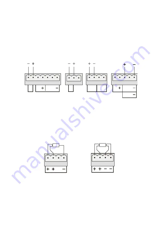
5.1 Wiring up thermistor sensors
Individual plug-in terminal blocks with cable restraints are provided to
make the connections to the inputs on the datalogger. Thermistors often
have no designating letters, since they have no polarity.
o
c
v
thermistor
sensor
thermistor
sensor
o
o t
t
thermistor
sensor
o
c
v
t
thermistor
sensor
451/851
Note: The
‘-’ denotes the ground connection. This should be connected to
the cable screen, if any.
5.2 Wiring up platinum resistance sensors
Individual plug-in terminal blocks with cable restraints are provided to
make the connections to the inputs on the datalogger. 1000 Series
loggers support both 3 and 4 wire PT100 sensors, and may be marked in
either of the two ways shown below.
3 wire connection
sensor
4 wire connection
sensor
N.B. It is essential for 3 wire sensors that the resistances of all the
connections are equal, i.e. the wires used for these connections should be
of the same material, gauge and length. This allows the circuit to cancel
the effects of lead resistance on the sensor measurement.


