Art.-Nr./Art. No./Réf./N° art/N° art.: 9010008B01M
Version
: 1.3
Date
: 29.08.2017
2/9
6
Exclusion of liability
No liability shall be accepted for any damage or operational faults caused by
a failure to observe these operating instructions. All further liability of the
manufacturer is excluded in the case of damage caused by the use of
replacement and accessory parts that have not been authorized by the
manufacturer.
No unauthorized repairs, conversions or modifications are permitted for reasons
of safety and the manufacturer shall not be liable for any resulting damage.
7
Function
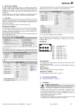
4 safety inputs safety inputs, that can be connected differently, connect the
safety and control outputs respectively depending on the configurable, logical
connection. In addition, there are two inputs available for reading external con-
tactors and start buttons.
Refer to the associated data sheet for the exact configuration.
Configuration options
On our website www.elobau.com eloFlex you will find the eloFlex Configura-
tor, which offers a step-by-step guide to derive your required configuration.
Clicking on underlined terms and functions serves to open an explanatory win-
dow to explain the items in more detail.
The micro-controller-controlled safety control unit can be delivered with the fol-
lowing configuration options.
Each component can be individually customised.
If an OSSD safety input is chosen, the (+) potential must be taken from termi-
nals 8, 16, 24, 32.
Upon selection of OSSD at the safety input a sensor with cross-short detec-
tion must be used or any errors resulting from cross-shorts must be ruled out.
A maximum of one external contactor input can be assigned to one safety
output.
Safety input 1-4
(NO/NO) (-/+)
e.g. protective door
(NO/NC) PL e (+/+) / PL d (-/+)
e.g. protective door
(NC/ NC) (-/+)
emergency stop switch
OSSD (safe semiconductor) (+/+)
safe sensors only with PNP
outputs e.g. light grid
External contactor /Start 1-2
automatic
Automatic start/restart with HIGH level
manual
Release at rising flank
manual
Release at falling flank
Safety output 1-4
Input
Logic *
Switch-on/switch
off delay in s
External monitoring
Safety input 1
AND
t
ON
,
s
___
t
OFF
,
s
Contactor/
start 1
Safety input 2
OR
Contactor/
start 2
Safety input 3
NAND
Safety input 4
NOR
XOR
XNOR
NOT
2-hand safety control 1 + 2
2-hand safety control 3 + 4
* When selecting the logic operator, ensure that the resulting function fulfils the
specified safety function and corresponds to the specified properties.
* Th control output is switched on after initialization.
No input is assigned when selecting BTR, error or safety output. The outputs’
switch-on/switch-off delay time of between 0.0 s and 99.9 s can be set in
0.1 second steps.
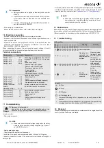
LED displays
Control outputs 1-4
Input
Logic
Switch-on/switch-off
delay in s
AND
t
ON
,
s
___
t
OFF
,
s
OR
NAND
Safety input 1
Safety input 2
Safety input 3
Safety input 4
NOR
XOR
XNOR
NOT
BTR*
ERROR
as for safety output 1
as for safety output 2
as for safety output 3
as for safety output 4
1
3
7
4
8
5
9
6
10
2
LED 1
LED 2
LED 3
LED 4
LED 5
LED 6
LED 7
LED 8
LED 9
Operability ("Ready")
Fault ("Error")
Safety input 1 ("I 1")
Safety input 2 ("I 2")
Safety input 3 ("I 3")
Safety input 4 ("I 4")
Safety output 1 ("O 1")
Safety output 2 ("O 2")
Safety output 3 ("O 3")
LED 10
Safety output 4 ("O 4")
Operating time
The operating time is the maximum time permitted on a sensor between actua-
tion of both sensor contacts.
With 2-hand operation, it is the maximum time permitted between actuation of
both sensors.
Safe condition
The safety outputs are opened or with high resistance.
Hazardous condition
The safety outputs are closed or with low resistance.
8
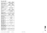
Technical specifications
See "Technical specifications" from page 15
.
9
Installation
- Installation of the safety control unit is only permitted in a voltage-free state.
- Ensure that the prescribed fuses (
see "Technical specifications"
) are used.
- Snap the safety control unit onto a mounting rail (DIN EN 60715 TH35) in the
switch cabinet. The safety control unit is fixed.
- Connect the safety control unit.
The pluggable terminal blocks can be coded by means of pins, the sockets
in the device are inversely coded by means of coding tabs.
Danger
Danger of electrocution!
Ensure that the safety control unit is installed and put into
operation only by specially trained, authorized personnel.


