

STC-1000X Microcomputer Temperature Controller User Manual
Overview
STC-1000X temperature controller features cooling and heating modes with automatic
switch, temperature unit switch between Celsius and Fahrenheit, temperature control
by set-point and differential, temperature calibration, cooling output protection delay,
sensor fault alarm and other functions. The controller reserves an interface of RS-485
communication function for further connection to an Elitech IoT module which makes
remote control available.
Specifications
Power Supply
Measurement Range
Temperature Resolution
Temperature Accuracy
Total Power Consumption
Operating Ambient Temperature
Storage Temperature
Relative Humidity
Relay Contact Output Rating
Sensor
Waterproof Grade Of Front Panel
Panel Size
Mounting Size
Product Size
Sensor Cable Length
Based on: 220V±10%, 50/60Hz;
110V±10%, 50/60Hz; 24VAC/DC; 12VAC/DC;
*
-50°C~120°C/-55°F~248°F
0.1°C
±1°C (-20°C~50°C)/±2°F, ±1.5°C/±3°F (others)
< 3W
0°C~60°C
-30°C~75°C
20%~85%RH (non-condensing)
Cooling/Heating: 10A/250VAC
NTC (10K /25°C, B value = 3435K)
IP65
80 x 35 mm
71 x 29 mm
80 x 35 x 66 mm
2m (probe length included)
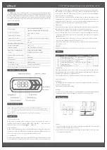
Operation
&
Display Panel
ON/OFF Button
Down Button
Temperature Unit Indicator
Set Button
Up Button
Cooling Indicator
Button Lock Indicator
Heating Indicator
Network Indicator
ON/OFF Indicator
Setting Indicator
Button Instructions
Quick Start
1. Unlock the keyboard
Under normal operating status, the buttons will be locked after 10 seconds of
inactivity, and the button lock indicator will be on. Hold button for more
than 3 seconds to unlock the buttons and will be off.
2. View parameters
Under normal operating status, press and release
▲
button to display the temperature
set-point; press and release
▼
button to display the temperature differential set-point.
The controller will be back to normal display status after 2 seconds.
3. Set parameters
Under normal operating status, press and hold button for more than 3 seconds
to enter parameter setting mode. The indicator will be on and the first code F1
/
Press and release: Back to previous menu
Hold for 3 seconds: Turn ON/OFF;
.
▲
Press and release: Display temperature set-point and back to normal display after 2 seconds.
▼
Press and release: Display temperature differential set-point and back to normal display after 2
seconds.
Hold for 3 seconds: Unlock the keyboard or enter parameter setting mode
.
/
/
/
/
will be displayed in the panel. Press
▲
or
▼
button to scroll up or down menu items
and display the corresponding code. Press button to display the current parameter
set-point. Press
▲
or
▼
button again to increase or decrease the value and press
to back to parameter code display.
If you need to save the settings, please press and release button and back to normal
display status. If not, just keep the controller inactive for 10 seconds, it will be back to
temperature display status. If an error occurs during saving settings, the panel will
display
Er
and back to temperature display status in 3 seconds.
4. Operations
Under normal operating status, the panel displays currently measured temperature
and automatically recognizes and switches cooling and heating modes.
- If measured temperature temperature set-point + temperature differential, and
compressor delay time F3, the controller starts cooling mode and indicator is on.
- If measured temperature temperature set-point, the controller stops cooling and
indicator is off.
- If measured temperature temperature set-point - temperature differential, the
controller starts heating mode and indicator is on.
- If measured temperature temperature set-point, the controller stops heating and
indicator is off.
5. ON/OFF
Hold the power button for more than 3 seconds to turn on/off the controller.
/
/
Menu
Code
Function
Setting Range
Default
Remark
F1
Temperature Set-point
-49~109°C/-56~228°F
10°C/50°F
3°C/37°F
0°C/0°F
3
0
1
Reserved
1~10°C/33~50°F
0~10 min
-10°C~10°C/-10~10°F
0: °C 1: °F
1~127
Temperature Differential
Compressor Start Delay
Temperature Calibration
Temperature Unit
Communication Address
F2
F3
F4
F5
F6
Fault
&
Alarm
When the temperature sensor is short circuit or open circuit, the controller will start
fault alarm mode and turn off all the outputs, the buzzer will beep and the panel will
display
EE
. Press any button to mute the buzzer.
The controller will return to normal operating mode after the fault is removed.
Safety Precautions
Important!
1. Distinguish the sensor lead, power cord and output relay interface. Do not connect
wrong or overload the relay.
2. Cut off power supply before wiring.
Warning!
Do not use the controller in water or too humid environment, or environments at high
temperature, with strong electromagnetic interference or strong corrosion.
Wiring Diagram
Caution!
1. The power voltage must be in accordance with the voltage labeled on the controller.
Please ensure the stability of power voltage.
2. Separate as much as possible the sensor lead from power cables to avoid possible
electromagnetic disturbance.
L
N
Sensor
Power
Heating
Cooling
* The details should be refer to the wiring diagram of actual device.