6
Operating the Device
98
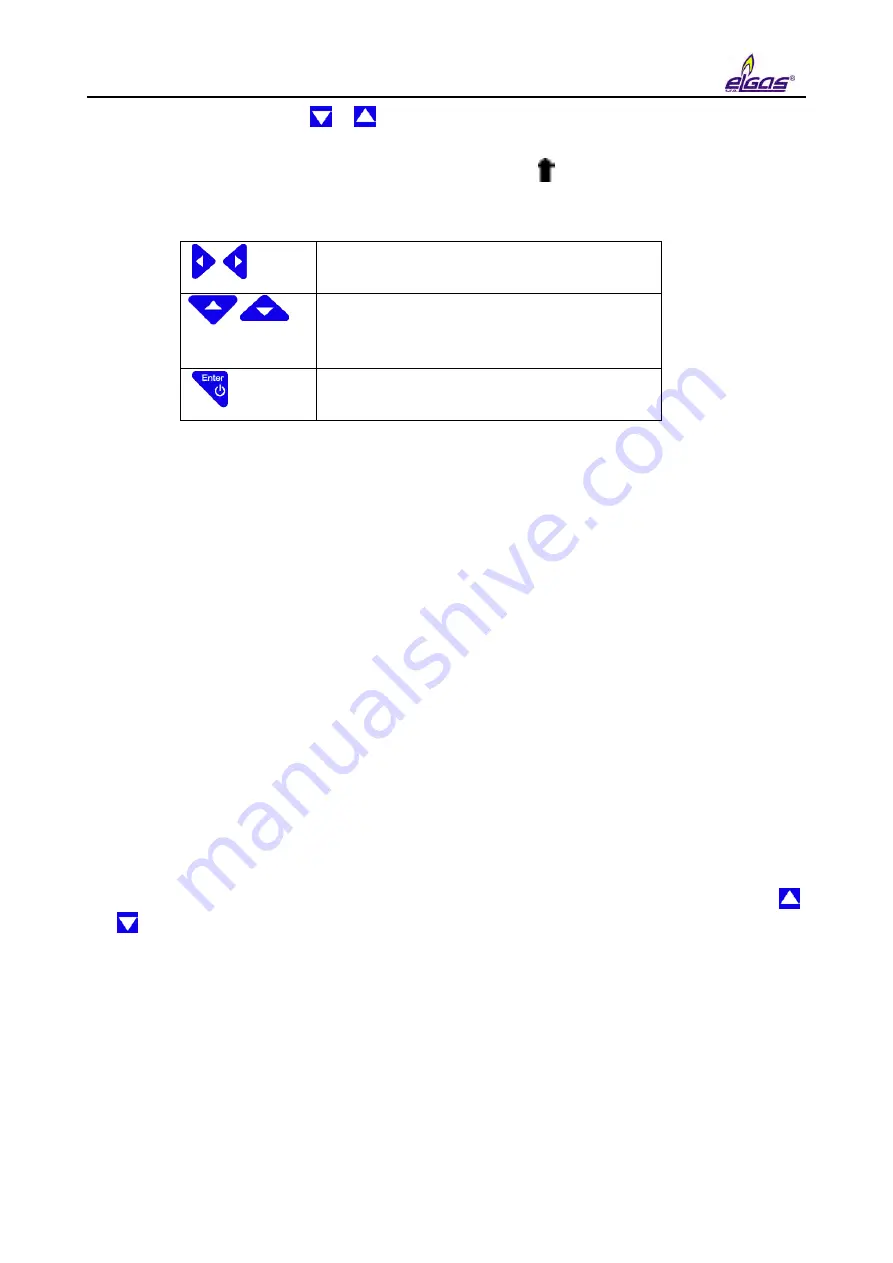
To edit a parameter, press the or keys to move the parameter to the first row on the display
(the parameter is displayed inversely). Start the editing by pressing the Enter key.
The edited position in the row is indicated with the symbol . The keys for parameter editing
have the following functions:
Selecting the edited position in the row
Selecting and entering an alphanumeric
character
(space, 0 to 9, A to Z, a to z)
End of editing the parameter
Saving the Parameters
After you finish editing the parameters, you need to enter the changes in your device. To do this,
choose "Save Parameters". Successful saving the parameters in the device is confirmed by the
message "Valid Data".
Totalizer values and Current time are saved immediately after entering the value. A confirmation
dialog is displayed before the value is saved, and on confirmation, the value is stored in the
appropriate register.
6.8 System data Menu
About Device
Device Reset
Communication
Frozen Values
6.8.1 About Device
The basic system parameters are displayed here, see Fig. 46. In addition, you can use the
and keys to display additional data (digital inputs and outputs, etc.).
6.8.2 Device Reset
The command is non-destructive. After selecting the device reset, the program jumps to the start
address and re-initializes the entire metering system. Neither the contents of all archives, nor the
values of all V and V
b
gas volumes change during this operation. The same applies to all the
other set parameters. The command execution is independent of the position of the service
switch.
Содержание DATCOM
Страница 38: ...3 Technical Parameters 36 ...
Страница 45: ...5 Installation and Commissioning 43 5 1 2 ELCORplus corrector Fig 2 ELCORplus device dimensions ...
Страница 50: ...5 Installation and Commissioning 48 Fig 7 Examples of data plates ...
Страница 83: ...5 Installation and Commissioning 81 Fig 37 Communication via RS232 RS485 using B RS module ...
Страница 115: ...7 Technical Description of the Device 113 Fig 57 Functional diagram of ELCOR ...
Страница 116: ...7 Technical Description of the Device 114 Fig 58 Functional diagram of ELCORplus ...
Страница 122: ...7 Technical Description of the Device 120 Fig 61 Modem replacement ...
Страница 139: ...7 Technical Description of the Device 137 Fig 65 Volume and energy calculations calculation scheme ...
Страница 159: ...10 Communication with the Device 157 packet ...
Страница 174: ...12 Accessories 172 Fig 78 ELCORplus example of use of external modules ...
Страница 175: ...12 Accessories 173 Fig 79 ELCOR example of use of external modules Fig 80 ELCOR example of use of external modules ...
Страница 211: ...Appendix 2 ELCORplus version for Zone 2 209 Fig 86 Block diagram ELCORplus for zone 2 with ext 230V power supply ...
Страница 213: ...Appendix 3 Compass Data Export 211 Preview of generated document ...
Страница 215: ...Appendix 3 Compass Data Export 213 3 Export to XLS 4 Export to TXT DOC ...
Страница 216: ...Appendix 3 Compass Data Export 214 ...
Страница 217: ...Appendix 3 Compass Data Export 215 5 Export of graph ...


