


Jupiter
EVM
Getting
Started
Rev
C01
:
05/17/2007
Copyright
Elevate Semiconductor 2012
Page 20 of 22
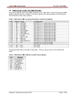
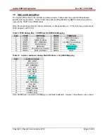
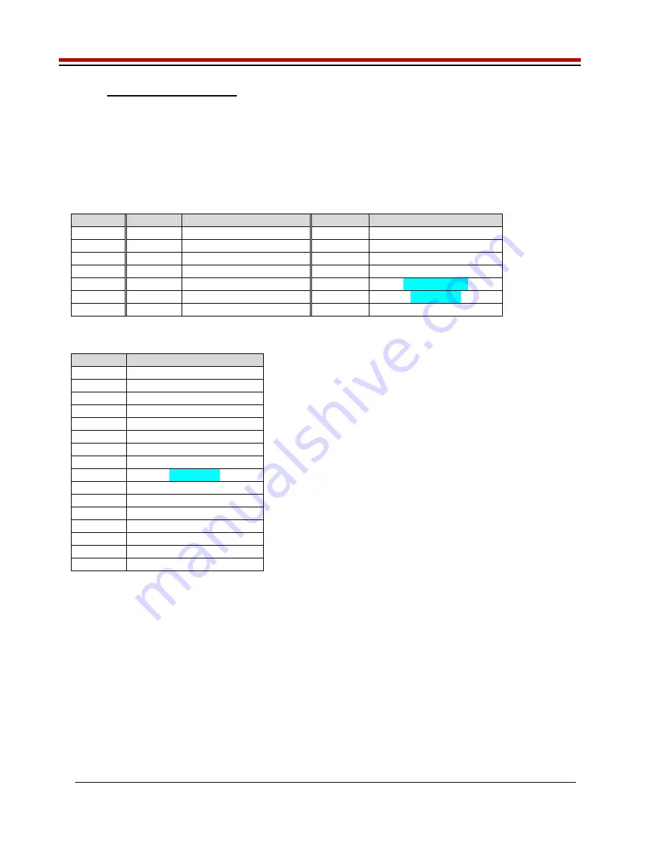
3.2 ADC and Analog Mux
The Octal FVMI contains a 24-bit ADC and analog muxes. Table 9 lists the Jupiter EVM loadboard
specific mux input sources. Table 10 lists the Jupiter EVM loadboard LB_AMUX analog mux which is
routed to the VINP13 and VINN8 nodes.
Note: Most signals go through channel protectors or voltage dividers (i.e. VCC) since they could exceed
FVMI Supplies (+20V/-15V).
Table 9: FVMI Analog Mux – VINPOS(A) & VINNEG(A) Mapping
Addr
VINP#
VINPOS(A)
VINN#
VINNEG(A)
7
VINP8
Reserved
VINN8
VREF Div Sense
8 VINP9 GANG_MON(p) VINN9
TJ
(Master)
9
VINP10
EXT_SENSE(p)
VINN10
LB_AMUX (see below)
10 VINP11
MONITOR(p)
VINN11
TJ
(Slave)
11 VINP12
SENSE(p)
VINN12
MON_REF(p)
12
VINP13
LB_AMUX (see below)
VINN13
GANG3(p)
13 VINP14 TEST_NODE(p) VINN14
REXT
Table 10: Jupiter Loadboard Analog Mux Definitions - LB_AMUX Mapping
Addr
Loadboard Amux
0 DUT_GND
1 VCCOUT_DIV
2 EXT_SENSE(p)
3 VCC_DIV
4 CAP_AP(p)
5 CAP_AN(p)
6 TN_DIV
7 CAP_SR(p)
8
GANG2(p)
9 CAP_BP(p)
10 EXT_FORCE(p)
11 VEE_DIV
12 CAP_BN(p)
13 RNET_SENSE
14 FORCE_A(p)
15 FORCE_B(p)
Note: Addr#8 was connected to SENSE(p) on the RevB loadboard. However, the software never used it.