


Jupiter
EVM
Getting
Started
Rev
C01
:
05/17/2007
Copyright
Elevate Semiconductor 2012
Page 13 of 22
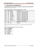
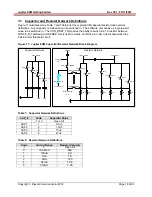
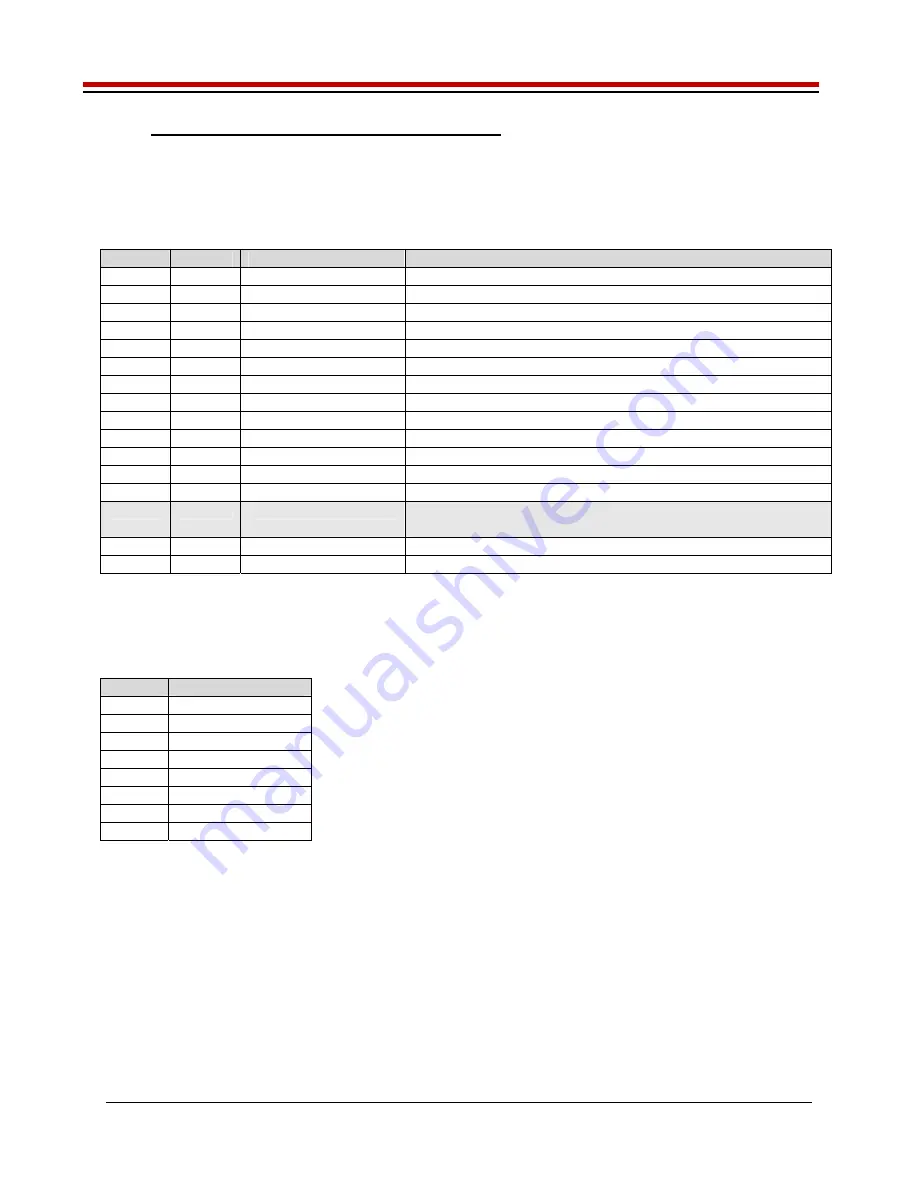
2.6 Motherboard Jumper and SMA Definition
Table 5 lists the Motherboard Jumper/SMA definitions for the Jupiter EVM. Only the EN (E3) jumper/SMA
would be optionally used by a customer. The other jumpers must be shorted between pin 1&2 (towards
back of board) to ensure proper operation.
Table 5: Motherboard SMA and Jumper Definitions (Jupiter Input Signals)
TC#
Jumper Usage
Configuration
TC30
E12
Reserved
Short Pin 1 & 2. towards back of board
TC29
E11
Reserved
Short Pin 1 & 2. towards back of board
TC28
E14
SDI_DATA
Short Pin 1 & 2. towards back of board
TC27
E15
SDI_SCK
Short Pin 1 & 2. towards back of board
TC26
E2
SDI_RCK
Short Pin 1 & 2. towards back of board
TC25
E10
Slave RESET
Short Pin 1 & 2. towards back of board
TC24
E9
Slave STB
Short Pin 1 & 2. towards back of board
TC23
E8
EXT_MON_OE
Short Pin 1 & 2. towards back of board
TC22
E7
Unused
Short Pin 1 & 2. towards back of board
TC21
E1
EXT_TJ_EN
Short Pin 1 & 2. towards back of board
TC20
E6
EXT_LD
Short Pin 1 & 2. towards back of board
TC19
E5
EXT_UD
Short Pin 1 & 2. towards back of board
TC18
E4
EXT_ADDR_CK
Short Pin 1 & 2. towards back of board
TC17
E3
EN
Short Pin 1 & 2: source from latch
Short Pin 2 & 3: source from SMA
TC16 E13
N/A
Don’t
care
TC15 E20
N/A
Don’t
care
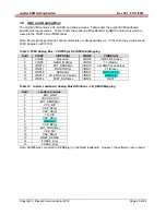
The following table defines the Jupiter output signals. These are always present at the motherboard
SMAs.
Table 6: Motherboard SMA Definitions (Jupiter Output Signals)
TC#
MB EVM
TC14 KEL_ALARM_N
TC13 V_ALARM_N
TC12 I_ALARM_N
TC11 OT_ALARM_N
TC9 ALARM_N
TC8 C_BIT_N
TC6 CAP_DIS_N
TC5 DPS_EN_N