


12 – Placing the Loudspeaker-Signal Through-Contact Standoffs
●
23
If you have enough transistors, it’s favorable to select the input tran-
sistors pairs T1/T2 and T3/T4 for identical U
BE
and h
FE
values. The
same applies to the transistors in the second differential amplifiers, T9/
T10 and T11/T12. See the end of this document for details (Section 17
– Selecting BC546B/BC556B for Differential Pairs). When soldering the
pairs, make sure the flat sides remain in good contact, since a maxi-
mum contact surface guarantees proper thermal coupling.
Next, the radial power resistors R50, R51, R54, R55, capacitors C15
and C16, and capacitors C20...C27 can be fitted and soldered.
12 – Placing the Loudspeaker-Signal
Through-Contact Standoffs
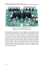
Figure 23. Two 30-mm M3 male-female standoffs are
attached to the pads of K3 and K4.
Содержание Fortissimo-100
Страница 7: ...Elektor Fortissimo 100 Power Amplifier Kit 8 Figure 2 The resistors and small capacitors in the kit ...
Страница 10: ... 11 Figure 7 The mechanical parts in the kit Figure 8 The SK104 heatsinks in the kit 1 Kit Contents ...
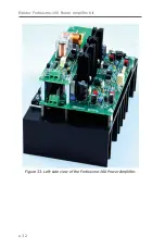
Страница 31: ...Elektor Fortissimo 100 Power Amplifier Kit 32 Figure 33 Left side view of the Fortissimo 100 Power Amplifier ...
Страница 32: ...15 Final Assembly 33 Figure 34 Right side view of the Fortissimo 100 amplifier ...
Страница 48: ...23 Schematics and PCB Layouts 49 Figure 46 Bottom side copper layout for both PCBs 210364 1 v1 1 ...


