background image

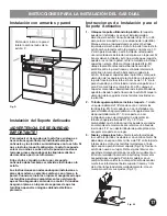
Installation with cabinets and wall

Anti-tip installation

To reduce the risk of tipping of the range, the range
must be secured to the floor by properly installed anti-
tip bracket and screws packed with the range. Failure
to install the anti-tip bracket will allow the range to tip
over if excessive weight is placed on an open door or if
a child climbs upon it. Serious injury might result from
spilled hot liquids or from the range itself.

If range is ever moved to a different location, the anti-
tip brackets must also be moved and installed with the
range.

Instructions are provided for installation in wood or
cement fastened to either the floor or wall.  When
installed to the wall, make sure that screws completely
penetrate dry wall and are secured in wood or metal.
When fastening to the floor or wall, be sure that screws
do not penetrate electrical wiring or plumbing.

IMPORTANT SAFETY WARNING!

Anti-tip bracket installation instructions

1.

Locate the Bracket Using the Template

 - (Bracket

may be positioned on either the left or right side of the
range.  Refer to Figs. 24 thru 26 to position the bracket
if template is not available). Mark the floor or wall
where left or right side of the range will be located. If
rear of range is against wall or no further than 1-1/4"
from wall when installed, you may use the wall or floor
mount method. If molding is installed and does not
allow the bracket to fit flush against wall, remove
molding or mount bracket to floor. For wall mount (Fig.
24), locate the bracket by placing the back edge of the
template against rear wall and the side edge of
template on the mark made referencing the side of the
range. Place bracket on top of template and mark
location of the screw holes in wall. If rear of range is
further than 1-1/4" from wall when installed, attach
bracket to the floor. For floor mount (Figs. 24 or 25),
locate the bracket by placing back edge of the
template where the rear of the range will be located.
Mark the location of the screw holes shown in
template.

2.

Drill Pilot Holes & Fasten Bracket

 - Drill 1/8" pilot

hole where screws are to be located (Fig. 23). If
bracket is to be mounted to the wall, drill pilot hole at
an approximate 20° downward angle. If bracket is to
be mounted to masonry or ceramic floors, drill 3/16"
pilot hole 1-3/4" deep. The screws provided may be
used in wood or concrete material.  Use 5/16" nut-
driver or flat head screwdriver to secure the bracket in
place.

3.

Level & Position Range

 - Level range by adjusting the

(4) leveling legs with a wrench. Note: A min. clearance
of 1/8" is required between bottom of range and
leveling legs to allow room for bracket. Slide range
back into position (Fig. 26). Remove lower panel or
storage drawer to visually check that rear leveling leg
is inserted into and fully secured by the bracket. For
models with a warmer drawer or broiler compartment,
grasp the top rear edge of the range and carefully
attempt to tilt it forward. Use a level to check your
adjustments (Fig. 27).

Fig. 23

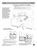
INSTALLATION INSTRUCTIONS FOR FREESTANDING DUAL FUEL

Fig. D

5

WALL

Minimum clearance to
side wall on either side
of appliance is 5”

30”

opening

width

Содержание EW30DF65G S

Страница 1: ...Installation Instructions 30 Free Standing Dual Fuel Instrucciones de Instalacion la Estufa a Gas Dual de 30 316454910 Rev C ...

Страница 2: ......

Страница 3: ...ot use any phone in your building Immediately call your gas supplier from a neighbor s phone Follow the gas supplier s instructions If you cannot reach your gas supplier call the fire department Installation and service must be performed by a qualified installer service agency or the gas supplier Important Note to the Consumer Keep these instructions with your Use Care Guide for futurereference As...

Страница 4: ...ynthetic floor covering make sure the floor covering can withstand heat at least 90 F above room temperature without shrinking warping or discoloring Do not install the range over carpeting unless you place an insulating pad or sheet of 1 4 inch thick plywood between the rangeandcarpeting To eliminate the need to reach over the surface burners cabinet storage space above the burners should be avoi...

Страница 5: ...e conduit for connection of the range Fig 19 Power cord 40 50 ampere rated Cord Kit 48 MAXIMUM LENGTH Fig 20 4 or 3 wire 40 50 ampere rated wall receptacle and mounting plate Fig 21 Copper electrical wiring and metal conduit for hard wiring installation only Tools you will need Wear safety glasses when using tools For leveling legs and Anti Tip Bracket Adjustable wrench or channel lock pliers Fig ...

Страница 6: ...d the bottom of the cabinets INSTALLATION INSTRUCTIONS FOR FREESTANDING DUAL FUEL Do not seal the range to side cabinets Do not pinch the power supply cord between the range and the wall If cabinet depth is greater than 25 the oven front frame must extend beyond cabinet front by 1 2 minimum All openings in the wall or floor where the range is to be installed must be sealed Install a flush mount 24...

Страница 7: ...o floor For wall mount Fig 24 locate the bracket by placing the back edge of the template against rear wall and the side edge of template on the mark made referencing the side of the range Place bracket on top of template and mark location of the screw holes in wall If rear of range is further than 1 1 4 from wall when installed attach bracket to the floor For floor mount Figs 24 or 25 locate the ...

Страница 8: ...in Installation Steps for 4 or 3 Wire connections This appliance must be properly installed and grounded by aqualifiedtechnicianinaccordancewiththeNationalElectrical CodeANSI NFPANo 70 latestedition andlocalelectrical coderequirements This appliance may be connected by means of permanent Hard Wiring or Power Supply Cord Kit When hard wiring do not leave excess wire in range compartment Excesswirei...

Страница 9: ... 30 31 32 2 Insert the end connectors for Line 1 Line 2 and Neutral and tighten securely to the terminal block IMPORTANT NOTE DO NOT LOOSEN the factory installed nut connections which secure the range wiring to the terminal block Electrical failure or loss of electrical connection may occur if these 3 nuts are loosened or removed 3 You must disconnect the ground strap Remove the factory installed ...

Страница 10: ...ctions ONLY A ground strap is installed on this range which connects the center terminal of the terminal block neutral to the range chassis The ground strap is connected to the range by the center lowest screw See Fig 34 The ground strap must not be removed unless national or local codes do not permit use of ground strap NOTE If the ground strap is removed for any reason a separate ground wire mus...

Страница 11: ...ion may occur if these 3 nuts are loosened or removed NOTE For 3 Wire Permanent Connections skip Steps 3 4 and continue with Step 5 3 4 Wire Permanent Connection ONLY Disconnect the ground strap Remove the factory installed ground screw plate to release the factory installed copper ground strap from frame of the appliance Cut and discard the copper strap from the terminal block KEEP the ground scr...

Страница 12: ...er togasPressureRegulator Figs 19 37 DonotallowthePressureRegulatortoturn on pipe when tightening fittings 4 Attach flexible Appliance Conduit to Flare Adapter on Pressure Regulator Figs 18 37 5 Install 2nd Flare Adapter to external manual Shut Off Valve Figs 19 37 6 Attach flexible Appliance Conduit to Flare Adapter on Shut Off Valve Fig 37 7 After making these connections check for gas leaks Tur...

Страница 13: ...lower set screw See Fig 40 Turn counterclockwise to increase flame size Turn clockwise to decrease flame size Test to verify if LO or LOW setting should be adjusted right front position ONLY 1 Push in and turn knob to lite until burner ignites 2 Push in and quickly turn knob to LOWEST POSITION 3 If burner goes out reset control to OFF 4 Remove the burner control knob 5 Use a thin bladed screwdrive...

Страница 14: ...e or warmer drawer or the lower panel area See Fig 41 When ordering parts for or making inquires about your range always be sure to include the model and serial numbers and a lot number or letter from the Serial Plate on your range The Serial Plate will also inform you of the rating of the burners the type of fuel and the pressure the range was adjusted for when it left the factory Before you call...

Страница 15: ... la estufa Verifique el suministro de energía eléctrica y la estabilidaddelpiso Esesencialqueseusenlasdimensionesquesemuestran Las dimensiones indicadas proveen los espacios libres mínimos La superficie de contacto debe ser firme y nivelada Use el Tipo de Combustible Adecuado Antes de Proceder Su estufa ha sido diseñada para funcionar con gas natural solamente NotasImportantesparaelInstalador Lea ...

Страница 16: ...úrese de que su estufa sea instalada y puesta a tierra en forma debida por un instalador calificado o un técnico de servicio Esta estufa debe ser puesta a tierra eléctricamente de acuerdo con los códigos locales o en ausencia de ellos con el Código Eléctrico Nacional ANSI NFPA No 70 última edición cuando es instalada en los Estados Unidos Vea las Instrucciones para la Puesta a Tierra en la página ...

Страница 17: ... amperios LARGO MAXIMO 48 Fig 20 Tomacorriente mural y placa de montaje tetra o trifilar para40 50amperios Fig 21 Alambre eléctrico de cobre y tubo de metal para instalaciónconcablespermanentessolamente Herramientas y Materiales Necesarios Cuando trabaje con herramientas use lentes protectores Paralostornillosniveladoresysoporteantivuelco Llave ajustable o pinzas ajustables Fig 5 Llave de tuerca d...

Страница 18: ... No selle la estufa a los armarios laterals No apriete el cable el éctrico entre la estufa y la pared Si la profundidad del gabinete es superior a 25 el marco delantero del horo debe extenderse por lo menos m ás all á de la parte delantera del gabinete Se deben sellar todas las aberturas de la pared o del piso donde se instale la estufa En esta area rayaka instale un tomacorriente elétrico mural e...

Страница 19: ...a colocando el borde trasero de la plantilla contra la pared trasera y el borde lateral de la plantilla en la marca hecha indicando el lado de la estufa Coloque el soporte sobre la plantilla y marque la ubicación de los agujeros de los tornillos en la pared Si la parte trasera de la estufa está a más de 1 1 4 de la pared cuando ya está instalada instale el soporte en el piso Para montaje en el pis...

Страница 20: ...e estufa use sujetacable de estufa o conector flexible Ver Fig 32 en la página 19 NOTA Use solamente alambre de cobre en la conexión al tablero de bornes Modelos que requieren el Juego de Cable de Alimentación Eléctrica PUEDE OCURRIR RIESGO DE INCENDIO O CHOQUE ELECTRICO SI SE USA UN JUEGO DE CABLE DE ESTUFA DE CALIBRE INCORRECTO SI NO SE SIGUEN LAS INSTRUCCIONES DE INSTALACION O SI NO SE USA EL S...

Страница 21: ...e bornes Se puede producir una falla eléctrica o pérdida de la conexión eléctrica si estas 3 tuercas son aflojadas o retiradas 3 Usteddebedesconectarlacintadeconexiónatierra Retire el tornillo y placa de tierra instalada en la fábrica para soltar la cinta de conexión a tierra de cobre del marco del electrodoméstico CONSERVE el tornillo de tierra 4 Conecte el alambre de puesta a tierra Verde con el...

Страница 22: ...se retira la cinta de conexión a tierra se debe conectar un alambre de tierra separado al tornillo de tierra instalado en el chasis de la estufa y a una tierra adecuada CONEXIONES DEL CABLEADO PERMANENTE TRIFILAR Y TETRAFILAR 3 Conexión trifilar permanente siga los pasos 1 2 y 5 incluidosacontinuación 4 Conexión tetrafilar permanente siga los pasos 1 al 5 que se encuentran más abajo Antes del cabl...

Страница 23: ...te la cinta de conexión a tierra Retire el tornillo y placa de tierra instalada en la fábrica para soltar la cinta de conexión a tierra de cobre del marco del electrodoméstico CONSERVE el tornillo de tierra la placa de tierra y siga con el Paso 4 4 Conexiónpermanentetetrafilar SOLAMENTE Conecte el alambre terminal de puesta a tierra Verde al marco del electrodoméstico usando el tornillo y la placa...

Страница 24: ...e el suministro de gas a la estufa Figs 16 y 37 3 Instaleunadaptadorabocinado enelreguladorde presión del gas Figs 19 y 37 No permita que el regulador de presión gire en la tubería cuando esté apretando los accesorios 4 Instale el conducto flexible del artefacto en el adaptador abocinado en el regulador de presión Figs 18 y 37 5 Instale un segundo adaptador abocinado en la válvula de cierre extern...

Страница 25: ...UE ENTREN DERRAMES ALIMENTO AGENTES DE LIMPIEZA NI NINGUN OTRO MATERIAL EN LA ABERTURA DEL PORTATOBERA Siempre mantenga las tapas de los quemadores y las cabezas de los quemadores en sus lugares cuando se usen los quemadores superiores 1 2 quemadores estandar 9 500 BTU 2 Min 2 Max quemador doble 18 000 BTU 3 Quemador grande 14 000 BTU 4 Quemador de fuego lento perfecto 5 000 BTU 23 Deslice cuidado...

Страница 26: ...a Guía de Uso y Cuidado para las instrucciones de limpieza Si es necesario sacar la estufa para limpieza o mantenimiento cierre el suministro del gas Desconecte el gas y el suministro eléctrico Si el suministro del gas o el suministro eléctrico no son accesibles levante ligeramente la estufa del frente y retírela de la pared Retírela solamente hasta donde sea necesario para desconectar el gas y la...

Страница 27: ...blank ...

Страница 28: ......

Отзывы: