background image

4

To reduce the risk of fire, electrical shock, or injury when using your potwasher, please follow these basic pre-
cautions including the following:

Read all instructions before using your potwasher.

This Manual does not cover every possible condition and situation that may occur. Use common sense and caution 
when installing, operating and maintaining this appliance.

Do not sit, stand or lean on the door or racks of a potwasher.

Store potwasher detergent and rinse agents in clearly marked packages with MSDS (Material Safety Data Sheets) 
sheets in a safe place.

FOR YOUR SAFETY DO NOT STORE OR USE GASOLINE OR OTHER FLAMMABLE VAPORS AND LIQUID IN 
THE VICINITY OF THIS OR ANY OTHER APPLIANCE.

Your potwasher uses hot water to clean and sanitize a variety of wares. Machine surfaces and wares become hot 
during and immediately following normal operations. Operators should use caution when loading and unloading 
wares from the machine.

Do not touch the heating element during or immediately after use.

The installation of this unit must conform to local codes or, in the absence of local codes, to all National Codes gover-
ning plumbing, sanitation, safety and good trade practices.

BEFORE SERVICING, DISCONNECT THE ELECTRICAL SERVICE AND PLACE A RED TAG AT THE DISCON-
NECT SWITCH TO INDICATE WORK IS BEING DONE ON THAT CIRCUIT.

NOTICE:

 CONTACT YOUR AUTHORIZED SERVICE COMPANY TO PERFORM MAINTENANCE AND REPAIRS.

NOTICE:

 Using any parts other than genuine factory manufactured parts relieves the manufacturer of all warranty 

and liability.

NOTICE:

 Manufacturer reserves the right to change specifications at any time without notice.

WARNING:

 The equipment warranty is not valid unless the appliance is installed, started and demonstrated under 

the supervision of a factory trained installer.

WARNING:

 The unit must be installed by Personnel who are qualified to work with electricity and plumbing. Improper 

installation can cause injury to personnel and/or damage to the equipment. The unit must be installed in accordance 
with applicable codes.

SAVE THESE INSTRUCTIONS

A

SAFETY INSTRUCTIONS

Содержание 506029

Страница 1: ...CTIONS Pag 11 C1 WATER CONNECTION Pag 11 C2 ELECTRICAL CONNECTION Pag 11 C3 WARNING MESSAGES DISPLAYED ON THE CONTROL PANEL Pag 12 C4 DETERGENT RINSE AID DISPENSERS AND SETTINGS Pag 12 C5 SETTING THE DISPENSERS Pag 13 D USER INSTRUCTIONS Pag 15 D1 STARTING Pag 15 D2 WASH CYCLES Pag 16 D3 OPERATION Pag 16 D4 END OF WORK AND DAILY CLEANING Pag 18 D5 MAINTENANCE Pag 19 E TROUBLESHOOTING Pag 22 USA CO...

Страница 2: ...t touch the heating element during or immediately after use The installation of this unit must conform to local codes or in the absence of local codes to all National Codes gover ning plumbing sanitation safety and good trade practices BEFORE SERVICING DISCONNECT THE ELECTRICAL SERVICE AND PLACE A RED TAG AT THE DISCON NECT SWITCH TO INDICATE WORK IS BEING DONE ON THAT CIRCUIT NOTICE CONTACT YOUR ...

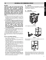
Страница 3: ... parts NOTICE FOR SHIPPING DAMAGE The container should be examined for damage before and during unloading The freight carrier has assumed responsibility for its safe transit and delivery If damaged equipment is received either apparent or concealed a claim must be made with the delivering carrier Apparent damage or loss must be noted on the freight bill at the time of delivery The freight bill mus...

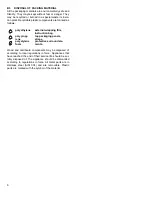
Страница 4: ...may be disposed of according to local regulations in force Appliances that have reached the end of their service life should be sui tably disposed of The appliance should be dismantled according to regulations in force All metal parts are in stainless steel AISI 304 and are removable Plastic parts are marked with the symbol of the material polyethylene external wrapping film instruction bag polypr...

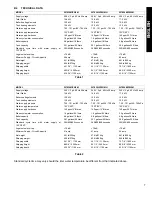
Страница 5: ... 16 1120 mm 44 1 16 1120 mm 70 7 8 1800 mm Shipping height 86 5 8 2200 mm 94 1 2 2400 mm 86 5 8 2200 mm Shipping depth 43 5 16 1100 mm 43 5 16 1100 mm 43 5 16 1100 mm Table 1 MODEL WT830M PW1M WT830H PW1MH WT850M PW2M Supply voltage 240 V 3 ph 60 Hz 39 amp 240 V 3 ph 60 Hz 39 amp 240 V 3 ph 60 Hz 49 amp Total Watts 14 8 kW 14 8 kW 17 5 kW Boiler heating elements 12 0 kW 12 0 kW 12 0 kW Tank heatin...

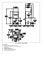
Страница 6: ...gend Figure 4 A Water inlet pipe with 3 4 dia 19mm fittings C Outlet pipe 1 5 8 ID 40 mm 11 16 ID 18 mm I Power supply S Detergent connection Q Equipotential Ground screw Only for model with free fall drainage Only for model with drain pump ...

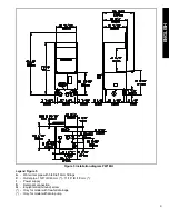
Страница 7: ...MH Legend Figure 5 A Water inlet pipe with 3 4 dia 19mm fittings C Outlet pipe 1 5 8 ID 40 mm 11 16 ID 18 mm I Power supply S Detergent connection Q Equipotential Ground screw Only for model with free fall drainage Only for model with drain pump ...

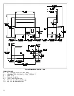
Страница 8: ...egend Figure 6 A Water inlet pipe with 3 4 dia 19mm fittings C Outlet pipe 1 5 8 ID 40 mm 11 16 ID 18 mm I Power supply S Detergent connection Q Equipotential Ground screw Only for model with free fall drainage Only for model with drain pump ...

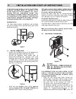
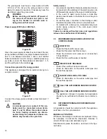
Страница 9: ...age connect the waste outlet pipe C Figure 4 Figure 5 Figure 6 to the main drain pipe using a trap or place the outlet pipe over an S trap set into the floor On models with drain pump position the outlet pipe at a height anywhere between 29 1 2 to 39 3 8 750 and 1000 mm from the floor Check that about 1 gallon 4 litres of water flow out of the outlet pipe during the rinse cycle Make sure drain hos...

Страница 10: ...s the manufacturer of all liability C3 WARNING MESSAGES DISPLAYED ON THE CONTROL PANEL NO WATER Check that the shutoff valve is open Check that the water inlet filter is clean Check the minimum main pressure is not less than 7 25 psi 50kPa Check that the overflow pipe is inserted INSUFFICIENT DRAINAGE Check if the overflow has been removed Check for obstruction on the waste outlet pipe and the ove...

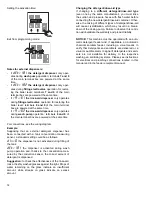
Страница 11: ...taneously for 5 seconds Display of programming mode Initial amount of detergent Setting the activation time Initial amount of rinse aid Setting the activation time Amount of detergent during the cycle Setting the activation time Amount of rinse aid during the cycle DETERGENT DISPENSER RINSE AID DISPENSER LEGEND Increase Decrease Confirm or select next parameter 3 2 1 3 3 2 2 1 1 3 2 1 3 2 1 3 2 1 ...

Страница 12: ...hanks to the concentration mea sured by the conduction sensor the correct amount of detergent is dispensed Suggestion to check the effectiveness of the rinse aid look at freshly washed glasses against the light Drops of water remaining on the glass indicate an insufficient amount while streaks on glass indicate an excess amount Changing the detergent rinse aid type If changing to a different deter...

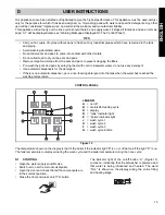
Страница 13: ...ith cold or lukewarm water do not use any detergent Use automatic dispensers for the detergent If there is no automatic dispenser pour a non foaming detergent into the tank when the water has reached the washing temperature CONTROL PANEL Figure 12 The temperature shown on the display is that of the boiler if the indicator light E is on or of the tank if the light D is on The tank temperature is di...

Страница 14: ...e may be personali sed e g increase of the rinse time and temperature The cycle times should only be set by an Authorized Service technician D3 OPERATION The filling and heating stage has finished when the dis play shows the tank temperature The appliance is then ready for use Open the door Pour the required amount of detergent into the tank Insert the dirty pots and pans upside down on the basket...

Страница 15: ...mended For normally dirty pots and pans press H button Figure 12 see table of times Cycle III For very dirty pots and pans press F button Figure 12 see table of times Cycle IV For particularly dirty pots and pans with dried food resi due pans with a special shape or for other specific needs of the user press G button Figure 12 which initiates a continuous wash until the operator selects an automat...

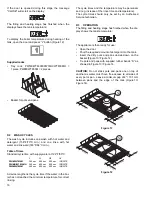
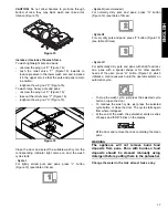
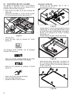
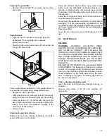
Страница 16: ...he display Switch off the potwasher by pressing A button Figure 12 Switch unit off at the main circuit breaker Close the water shutoff valve Replace the filters and the overflow Cleaning the nozzle jets Remove the top and bottom jets F and I unscrewing the ring nut H Figure 18 Unscrew plugs L from the rinse jets and clean using a water spray Do not use sharp implements to clean the nozzle holes wh...

Страница 17: ... thoroughly using a wet cloth and care fully wipe dry Clean the control panel using a soft damp cloth and a neutral detergent if necessary Do not wash the appliance using direct or high pressure water jets To reduce the emission of pollutants into the environment clean the appliance externally and where necessary internally with products having a biodegrada bility of over 90 Leave the door opened ...

Страница 18: ...and discarge the tank Close the door and start the Cycle III by pressing F button Figure 12 The wash cycle duration is 6 minu tes At the end of the cycle the potwasher emits a series of beeps and END blinks on the display CAUTION observe chemicals producers instruc tions handling appliance where chemicals have been used CAUTION do not allow the deliming agent to remain in the machine longer than r...

Страница 19: ...l war ranty and liability NOTICE Manufacturer reserves the right to change spe cifications at any time without notice WARNING The equipment warranty is not valid unless the appliance is installed started and demonstrated under the supervision of factory trained installer WARNING The unit must be installed by Personnel who are qualified to work with electricity and plumbing Improper installation ca...

Страница 20: ...the pans are stacked correctly in the racks EXCESSIVE FOAM IN THE TANK 1 Check that the wash water temperature is not less than 149 F 65 C 2 Check if the amount of product dispensed by the detergent dispenser is excessive see setting the dispensers paragraph 3 Ensure that the tank has not been cleaned with unsuitable cleaners Drain the tank and rinse thoroughly before new wash cycles 4 If a foamin...

Отзывы: