


22
SBMS0
SBMS0
www.ElectroDacus.com
www.ElectroDacus.com
11 User interface
11 User interface
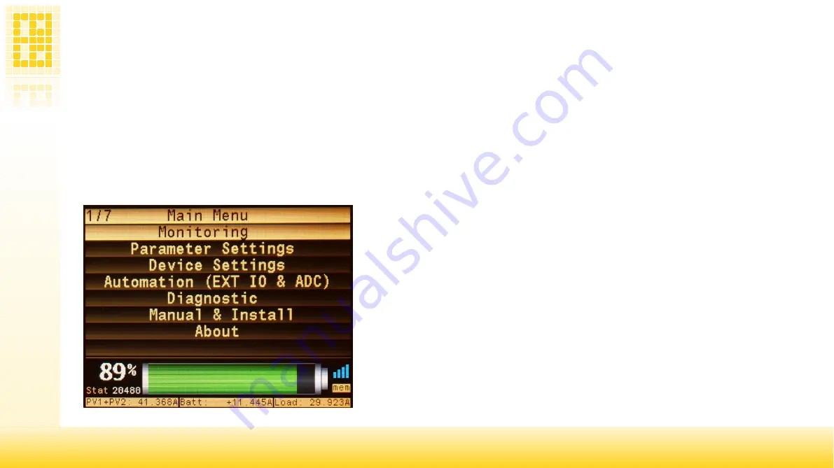
11.1 Main menu
11.1 Main menu
At power on the SBMS will be on main menu and this can also be access later from any other sub-menu by pressing the menu button on top.
The same Menu button has a dual function and if you keep that button pressed (is a touch button so touched) for about 5 seconds you can power
ON or OFF the Load and Charge FET's.
You will also be able tho see the most important information on the bottom part of the screen (that part is present in most menus).
The bottom part contain SOC level in numeric and graphic form the SBMS status represented by a number, the WiFi and internal data log “mem”
symbols. The lowest part will indicate if charge and discharge FET's are active by highlighting or not the PV and Load and you also have the
current for PV, Battery and Load.
* SOC (State Of Charge)
indication will be set automatically to 50% (49%) when you
connect the SBMS to battery for the first time since SBMS can not guess the state of
charge based only on cell voltage.
After the first full charge (on battery type 1 when highest cell gets to 3.53V and EOC
flag will be set the battery SOC will jump to 100% ) from that point SOC indication will
represent the real value.
Содержание DSSR20
Страница 1: ...1 user manual user manual v0 95 www ElectroDacus com www ElectroDacus com SBMS0 SBMS0 SBMS0 DSSR20 ...
Страница 43: ...43 ...
Страница 44: ...44 ...
Страница 45: ...45 ...


