


© ElectroCraft 2022
38
CPP-x06V48A-SA-CAN Drive User Manual
The CAN enable input can be configured using CompleteArchitect
TM
and has the following options:
a)
Not used
: The drive will ignore this input.
b)
Enable CAN
: This will enable the CAN operation. The drive will not transmit or receive any
messages on the CAN bus without this input enabled.
c)
Enable Drive
: T
he input can be used as the drive’s enable input instead of the default enable
input on the I/O connector.
d)
Enable CAN and Drive
: Use this input to enable both CAN and the drive.
10.1.4 CAN Address Settings
To receive Axis Messages on the CAN bus network, the drive must have a valid non-zero AXIS-ID. The
Axis ID is non-volatile and needs to be set just once. Axis IDs in the range 1-127 are available.
The AXIS-ID can be set either:
a) Assigned by CompleteArchitect
TM
.
b) In hardware using the Axis ID 4 position switch on the drive (SW1). Axis IDs in the range 1-15 are
available by this method. See table below.
SW ID
Name
Description
ID1
ADDR0
Hardware CAN Axis ID bit 0
ID2
ADDR1
Hardware CAN Axis ID bit 1
ID3
ADDR2
Hardware CAN Axis ID bit 2
ID4
ADDR3
Hardware CAN Axis ID bit 3
c) CAN Axis ID configured in CompleteArchitect
TM
as a base address plus hardware switches.
d) Dynamically assigned at power up over the CAN bus.
As shipped from the factory, standard ElectroCraft drives are configured with the hardware CAN address
switch set to 0 and a software AXIS-ID of 0. This is a null AXIS-ID and means the drive will not respond to
any Axis Messages until either a non-zero AXIS-ID is set per one of the above methods.
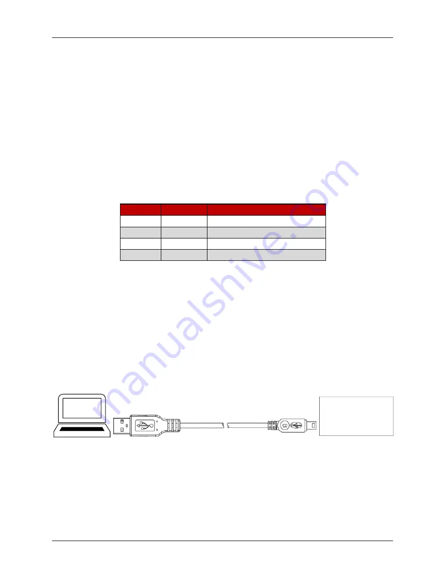
10.2 Connecting USB
An USB Type A Male to Micro USB Type B Male cable is required to connect the drive to the PC
software. Insert the USB Type A Male connector to the computer and Micro USB Type B Male to the drive
as shown in Figure 31. Follow steps as specified in CompleteArchitect
TM
user manual to establish
communication between PC software and drive.
USB Type A - Male
USB Micro Type B - Male
PC Software
Drive
Figure 32: USB cable connection between computer and drive


