


© ElectroCraft 2022
32
CPP-x06V48A-SA-CAN Drive User Manual
9
Connecting I/O
9.1
I/O Functional Description
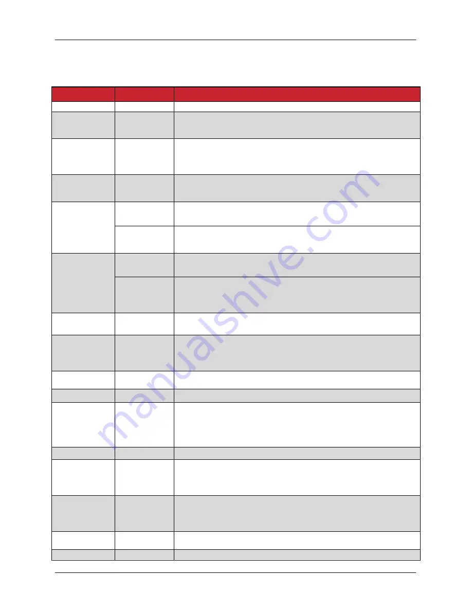
I/O Pin Name
Type
Functional Description
Frame
-
Shield Connection.
Analog Input
Positive 1
Analog Input
-10V to +10V input signal for speed or current command. The scaling
of input voltage to motor output is configured in the
CompleteArchitect
TM
.
Analog Input
Negative 1
Analog Input
-10V to +10V input signal for speed or current command. The scaling
of input voltage to motor output is configured in the
CompleteArchitect
TM
. For a single ended analog signal connection,
this pin should be connected to ground.
Analog Output
Analog Output
-10V to +10V output signal which represents the motor speed or
current. The scaling of motor output to output voltage is configured in
the CompleteArchitect
TM
.
Step
Analog Input
Positive 2
Digital Input
The rising edge of each input pulse is accepted as one step pulse by
the drive.
Analog Input
-10V to +10V input signal for use of a secondary feedback. The
scaling of input voltage to motor output is configured in the
CompleteArchitect
TM
.
Direction
Analog Input
Negative 2
Digital Input
When the input signal is active low, it reverses the speed or current
command. This in turn changes the direction of motor rotation.
Analog Input
-10V to +10V input signal for use of a secondary feedback. The
scaling of input voltage to motor output is configured in the
CompleteArchitect
TM
. For a single ended analog signal connection,
this pin should be connected to ground.
eBrake
Digital Output
Open drain output that can be used to engage electromechanical
brake. See section 12 for more details.
Capture
Digital Input
When the capture input pin has been triggered, it provides an
instantaneous encoder count location. The trigger occurs on a falling
edge input. The count location is stored in memory and can be
accessed via USB or CAN.
Fault
Digital Output
Open collector output that pulls to ground when the drive is in a
faulted state.
Ready
Digital Output
Open collector output that pulls to ground when the drive is ready.
Enable
Digital Input
Input which enables the drive when an active low signal is applied
and disables the drive when a high signal is applied. The signal
needs to be kept low for the drive to remain enabled. In case of any
drive interruptions or faults, this input should be toggled from high to
active low to re-enable the drive.
Brake
Digital Input
Input pin which dynamically brakes the motor when it’s active low.
Limit Switch
Positive
Digital Input
Input pin which controls the positive current delivered to the motor.
When the Limit switch positive is active low, the drive stops delivering
positive current to the motor. This will inhibit the torque in the positive
direction.
Limit Switch
Negative
Digital Input
Input pin which controls the negative current delivered to the motor.
When the Limit switch negative is active low, the drive stops
delivering negative current to the motor. This will inhibit the torque in
the negative direction.
+5 Vout
Output
Internally gen5 volts for customer use. Refer to section
4.3.2.
Ground
-
Referenced to supply ground.


