Elcometer PG70ABDL Скачать руководство пользователя страница 19

18

en

Memory capacity

You can create and save as many data files as required up to the maximum capacity of the gauge
memory (32 Mbit). If you try to create a new file which exceeds the memory capacity, the gauge will
display an error message. Saved data must be deleted in order to make the space available. 

11.7 CREATING A NEW DATA LOGGER FILE - GRID FORMAT 

To create a GRID log data file:
1.

Select MENU/DATA/NEW and press ENTER to continue

2.

Fill in a name and a note (if desired) for your data logger file

3.

Select the size of the grid. Grid positions are denoted by a number and a letter, where the
letter is the column and the number is the row. 
Use TOP LEFT and LOWER RIGHT to define the size of the grid. For example, a with the TOP 
LEFT set to A001 and LOWER RIGHT C003 would produce a 3x3 grid
The grid can have a maximum of 52 columns and 999 rows

4.

Set the Auto Increment direction. This option allows you to select which direction the cursor
moves after a reading is stored in terms of compass points. For example NORTH would move
the cursor up a row, and WEST would move a column left.

5.

Choose whether to activate SAVE GRAPHICS or not (snapshot of the A OR B scan on
screen).

6.

Finally create the log by scrolling to CREATE LOG, pressing ENTER and then OK to confirm.

The measurement grid is now displayed along with the grid name on screen.

11.8 HANDLING LOGGER FILES

Once created, logger files may be opened or closed using the functions "OPEN" and "CLOSE" 
Closing logger files places the gauge in immediate mode and will prevent accidental saving of data
into an inappropriate log.

11.9 STORING READINGS IN A DATA LOGGER FILE

1.

Create a new data logger file or open an existing file.
The grid is displayed in the lower half of the measurement screen.

Note: Once the file is open, it will remain open until it is closed or another file is opened. If the 
gauge is switched off, the file will be opened automatically when the gauge is switched on 
again. Press the ENTER key to display the file from the measurement screen.

2.

If you want to save the reading to a particular cell location, scroll to the desired cell.

Note: The cell location must be empty. If it already contains a reading and you want to save a 
new reading to the same location, refer to the instructions given in “Viewing and Deleting 
readings” on page 19.

3.

Take a reading and then press ENTER.
The reading value is saved in the file at the location selected and the cursor advances to the 
next cell according to the rules set for the data logger file:

If INCR. DIR is set to NORTH, EAST, SOUTH or WEST, the cursor will advance one cell in 
the chosen direction. When the cursor reaches the last cell in the row or column it will 
return to the other end of the row or column.

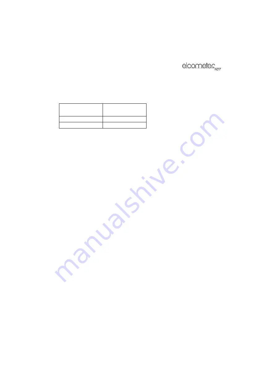
Save Graphics Option

Memory Capacity 

(readings)

On

12 000 +

Off

210 000 +

Содержание PG70ABDL

Страница 1: ...0 en Model PG70ABDL Precision Gauge Operating Instructions...

Страница 2: ...re available to download via our website Elcometer NDT Ultrasonic Couplant Material Safety Data Sheet www elcometerndt com images MSDS elcometer_ultrasonic_couplant pdf Elcometer NDT Ultrasonic Coupla...

Страница 3: ...ing Readings 14 9 Gates 15 10 Thru Paint Measurement Technique 16 11 Measurement Options 16 12 Gauge Setups 20 13 Data Transfer Software 22 14 Storage 22 15 Maintenance 23 16 Technical Specification 2...

Страница 4: ...measured The Elcometer PG70ABDL includes a data logging memory facility which allows readings to be stored in batches before being downloaded to a computer 1 1 STANDARDS Your gauge can be used in acco...

Страница 5: ...a change or selection If your gauge is displaying a grid log this key toggles an advance to row number option In the MENU MEAS and EDIT functions this key acts as a back or escape function If your gau...

Страница 6: ...apply couplant to the connecting end of the delay line before screwing together The transducer transmits and receives ultrasonic sound waves that the gauge uses to calculate the thickness of the mater...

Страница 7: ...displayed in English Spanish and German 1 Select MENU SETUP LANGUAGE and adjust with LEFT and RIGHT arrows Press once to access the menus then press to scroll to the right along the sub menu bar and t...

Страница 8: ...asurement screens A Battery Icon Remaining battery life B Repeatability Stability Indicator This indicator is used in conjunction with the digital thickness values displayed When all the vertical bars...

Страница 9: ...surface It can also be a useful view when scanning for pits and flaws The B Scan display is equipped with a scan bar representing the overall thickness The scan bar gives the user a visual indication...

Страница 10: ...value 3 Press MEAS to return to the measurement 5 7 GAIN The gain the amplitude of the transmitted pulse can be adjusted to suit a variety of applications To obtain valid readings the gain must be se...

Страница 11: ...dge Centre on www elcometerndt com 5 10 FRONT PANEL LIGHTS The green light illuminates when the alarm mode is active and the measured thickness is within limits The red light illuminates when the alar...

Страница 12: ...nt range and the back wall echo is less likely to be lost in the ring down or noise from the interface echo The pictures show typical A scans when measuring in interface to echo and echo to echo respe...

Страница 13: ...ucer type with the newly selected transducer type You now need to perform a probe zero before taking measurements 7 2 TRANSDUCER ZEROING Note This function is only used when using a contact style tran...

Страница 14: ...n uses two samples of different thicknesses with enhanced accuracy over small ranges close to the sample thicknesses used For the highest measurement accuracy use the known thickness calibration as th...

Страница 15: ...and DOWN arrows 4 Press OK to calculate the velocity and return to the measurement screen or ESC to cancel Note Place the transducer back on the calibration point The thickness reading should now matc...

Страница 16: ...ly beneath the transducer If the stability indicator has fewer than five bars showing or the numbers on the display seem erratic check to make sure that there is an adequate film of couplant beneath t...

Страница 17: ...elect MENU UTIL AUTO FIND 11 2 HIGH SPEED SCAN Although your gauge excels at making single point measurements it is sometimes desirable to examine a larger region searching for the thinnest point The...

Страница 18: ...ption of displaying the waveform filled in black or outlined unfilled To set this option 1 Press MENU select DISP select VIEW and then select RECT to set the RECT display view 2 Press MENU scroll to t...

Страница 19: ...displayed along with the grid name on screen 11 8 HANDLING LOGGER FILES Once created logger files may be opened or closed using the functions OPEN and CLOSE Closing logger files places the gauge in i...

Страница 20: ...scroll to the cell location press CLR and then OK or ESC to cancel The reading is deleted and if you wish you can now take another measurement and save the reading in this cell location 11 11 EDITING...

Страница 21: ...e software includes a default setup file that can be uploaded to the gauge at any time to restore factory settings However you should consider saving modified setups to an empty location rather than o...

Страница 22: ...ss ENTER The setup list screen is displayed 5 Scroll through the list of setups until the required location to save the setup is highlighted 6 Press OK to activate the confirmation screen 7 Press OK t...

Страница 23: ...with the latest version of firmware 13 1 2 USB to Serial Converter Some newer laptop computers do not have standard serial ports In this case use the USB to Serial converter supplied with the gauge 1...

Страница 24: ...ometer NDT supplier or directly to Elcometer NDT The warranty will be invalidated if the instrument has been opened 15 2 TRANSDUCER The transducer will wear with repeated use Transducer life depends o...

Страница 25: ...in s Thickness 0 001 mm 0 0001 or 0 01 mm 0 001 selectable Velocity Calibration Range 1250 m s to 10000 m s 0 0492 in s to 0 3937 in s Weight including batteries 380 g 13 5 oz Dimensions W x H x D 63...

Страница 26: ...s you specific legal rights and you may also have other rights which may vary from country to country state to state or province to province 17 2 OBTAINING SERVICE DURING WARRANTY PERIOD If your hardw...

Страница 27: ...ep 2 5 25mm TW 24007 Replace with S1018 1018 Steel Block A Aluminium Block SS Stainless Steel Block T Titanium Block 18 3 ULTRASONIC COUPLANT Each gauge is supplied with a 120ml 4oz bottle of standard...

Страница 28: ...5232 0 206 PVC 2388 0 094 Copper 4674 0 184 Quartz Glass 5639 0 222 Epoxy Resin 2540 0 100 Approx Rubber Vulcanised 2311 0 091 German Silver 4750 0 187 Silver 3607 0 142 Glass Crown 5664 0 223 Steel...

Страница 29: ...ONE POINT Performs a single point calibration This function allows you to automatically calculate the velocity by entering a known sample thickness TWO POINT Performs a two point calibration This func...

Страница 30: ...cho GATE 1 Set the value of Gate 1 Gate 1 can be used in pulse echo echo echo and interface echo measurement modes GATE 2 Set the value of Gate 2 Gate 2 can be used in echo echo and interface echo mea...

Страница 31: ...is value a red light will illuminate and the alarm will sound XFER TRANSFER BACKUP SET UPS Allows you to backup the setups currently stored in your gauge to a computer via the RS232 port RESTORE SETUP...

Отзывы: