ELCOM Uniq 150 Скачать руководство пользователя страница 31

54


Elcom, spoločnosť s ručením obmedzeným, Prešov

Elcom, spoločnosť s ručením obmedzeným, Prešov 


55

Uniq 150


               Service manual

Service 

manual 


Uniq 150

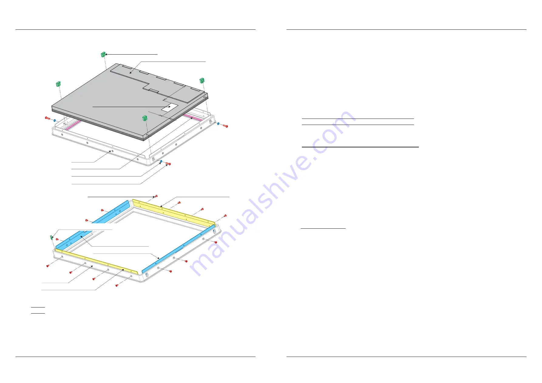
Figure 2.25.3. – Replacement of display with capacitive touch panel

33,5

96

Serrated lock washer M3 DIN6798

Screw M3 × 12 mm BN13255

LCD clip

Capacitive panel 15“ vandal proof

Tape TESA 4957 6 mm

Front cover

Insulation foil 25 × 12,5 × 0,25 mm

LED KM-2520VGC-A03 green

Screw M2,5 × 5 mm DIN965

Metal joining strip PP5000 TL

Front cover

Metal joining strip L PP5000 TL

Metal joining strip P PP5000 TL

Metal joining strip PP5000 TL

Note: 

It is possible to use prepared maintanace sets of front panels  Maintanace sets without display are primary used 

for models with AUO display version, but they can by used for Turbo touch too.

In case of AUO verzion, there is neccesary to take out original display.

P280180000     Touchpanel resistive  black frame-black multi TL without display

P2801800000   Touchpanel resistive  white frame-white single TL without display

P2801800001   Touchpanel resistive  gray frame-white single TL without display

P2801800002   Touchpanel resistive  gray frame-black multi TL without display

Next sets are installed by display:

P2801800005 Touchpanel resistive  black frame-black multi TL with display

P2801800006 Touchpanel resistive  white frame-white single TL with display

P2801800007 Touchpanel resistive  gray frame-white single TL with display

P2801800008 Touchpanel resistive  gray frame-black multi TL with display

2.26. LED replacement and interconnection

2.26.1. Replacement and interconnection of lightguide


The lightguide consists only execution with AUO kit. The lightguide will be most likely demaged if  the 

lightguide is necessary to remove or is needed to replace some of the LED diodes.

It is necessary prepare before replacement:

– 

tools for breaking removal of the lightguide and tools to clean lightguide remains the front cover

– 

tin and soldering

– 

Silicone OTTOSEAL black vandal – M990144

– 

Power glue Loctite 401 – M250007

– 

Tubing 2,4 mm – M010004

Process of replacement:


The lightguide is stick to the front cover with power glue and gaps between lightguide and cover are 

filled with silicone because of IP protection.
1. 

Truss and nick the lightguide with thin flat tool (shaver or screwdriver).

2. 

Clean the cover of the remains of lightguide, silicone and glue.

3. 

Glue diodes with cable on a new lightguide. There is a resistor 220R 0,6W on each of LED diode anode 

to reduce the voltage.

4. 

Put lightguide into front cover and spread a little of power glue on three protruding tabs from inner cover 

side to fix lightguide in front cover.

5. 

Fill gaps between lightguide and front cover edge from outher side with silicone.

Note:  Installation of lightguide must be executed precisely according to figure. Note all the gaps are filled with 

silicone, otherwise IP54 protection class cannot be guaranteed!

Содержание Uniq 150

Страница 1: ...Uniq 150 Uniq 150 Service manual version 1 4 Elcom spolo nos s ru en m obmedzen m Pre ov...

Страница 2: ...s not undergone language proofreading This guide as well as any part of it may not be copied repro duced or otherwise circulated without the permission of the publisher All rights of the company Elcom...

Страница 3: ...luetooth and WiFi installation 30 2 13 1 Bluetooth installation 30 2 13 2 WiFi installation into hinge 31 2 13 3 WiFi installation into milled covers 32 2 14 Interconnection and installation of VGA po...

Страница 4: ...2 25 1 Replacement of AUO kit 50 2 25 2 Replacement of DLC display with eTurbotouch touch panel 51 2 25 3 Replacement of display with capacitive touch panel vandalproof 53 Note 54 2 26 LED replacement...

Страница 5: ...Elcom spolo nos s ru en m obmedzen m Pre ov 5 Service manual Uniq 150 1 General specification...

Страница 6: ...td WiFi Bluetooth 1 5 USB 1 4 RS 232 1 VGA audio PS2 VGA audio optional IrDA remote control USB touch panel only Data backup 2 5 HDD 160 GB old standard 2 5 HDD 320 GB new standard 2 5 HDD 500 GB opti...

Страница 7: ...Elcom spolo nos s ru en m obmedzen m Pre ov 7 Service manual Uniq 150 2 Structural part...

Страница 8: ...e Mounting process 1 Connect cables of the covers according to mainboard type display type and touch panel Description of interconnection is placed in the particular chapter Exact interconnection of t...

Страница 9: ...rofessional who are pro perly equipped for such an operation 2 2 Mainboard replace 2 2 1 N270 1 Release the screw of the Pico Power PCB the little one 2 Pico Power board is connected to mainboard with...

Страница 10: ...ively destruction of Uniq 150 Figure 2 2 2 D525 mainboard replace Heat material SARCON 50 GR HI 25 25 0 5 mm Heat material SARCON 100 GR HK 20 20 1 mm Mainboard Screw M3 4 mm DIN7985A Insulation pad P...

Страница 11: ...front panel display If another display type as DLC is used PCB invertor is not necessary Disconnect cables of PCB before its dismounting interconnection is described in particular chapter The PCB is c...

Страница 12: ...COM3 6 VGA audio mic slot for RAM CF1 Compact Flash CN4 miniPCI slot MB Wafer N270 TP AUO Figure 2 5 2 Interconnection for D525 and eTurbotouch MB Wafer D525 TP eTurbotouch 1 J1 RST_BTN USB1 PWR_BTN D...

Страница 13: ...v Uniq Skrutka M3 4 mm DIN7985A 2 7 Stand removal Division of Uniq 150 according to stand execution is described in chapter Hinge set 2 7 1 Nx executions Note After leg removal disconnect Uniq 150 fro...

Страница 14: ...al Service manual Uniq 150 Screw M3 4 mm DIN7985A Screw M4 10 mm DIN912 Connectors cover Leg Figure 2 7 2 Tx execution Hinge rear part Hinge front part Screw M5 16 mm DIN912 Tube Holder Uniq 150 Screw...

Страница 15: ...replace 1 It is necessary to release all Uniq 150 hinge in some cases It is possible to put out all hinge after open ing Uniq 150 leg and connectors removal just release four Allen screws 2 Pull out h...

Страница 16: ...X U Z Z P Y Y P X X U V V U Z Z P Y Y P X X Cuff Direct P Angled U P P U P P U U P P Stand Leg Lx Tube Holder TH L3 L3 L2 L1 L1 L3 TH TH TH L1 cables gap direction forward leg jambs direction forward...

Страница 17: ...2427 Reader cable must be tucked completly inside Figure 2 10 1 MS reader installation strips 4 4 102 4 4 102 Tx components adjustment Nx components adjustment Front cover strip left Front cover strip...

Страница 18: ...35 65 KM57 bottom cover Doublesided thick tape 9 20 mm USB RFID reader ID12 Box PS17 35 65 KM57 top cover RFID holder Doublesided tape Tesafix 4965 9 55 mm Screw M2 5 8 DIN965 ku e ov cca 150 2 5 4 S...

Страница 19: ...g 1 6 10 mm 4 M010003 Cable 8 wires 250 mm 28 AWG 2H 1 M200143 Tie EKB91N 2 3 M250009 Bluetooth USB key 1 M310015 USB extension cord AF AM 1 m 1 M200141 Consumes only half of cable and only in Tx exec...

Страница 20: ...GA port is connected to mainboard to connector VGA1 Uniq PC or to connector CN1 Uniq Display Owing to VGA connector installation for Nx execution is necessary to assembly extended connectors holder 2...

Страница 21: ...to COM connector It is necessary to install extended connector holder for Nx execution 2 15 1 Com ports interconnection for Nx execution 1 Dismount D SUB connector and solder it on cable 2 Mount D SUB...

Страница 22: ...and connectors cover The screws remains of previous step Connectors cables lead between holder and leg Interconnection of cables is described in particular chapter 5 Fix a new metal strips into the le...

Страница 23: ...thick tubing long at least 20 mm on 4 wires cable with PS2 connector 6 Solder both cables and soldered places cover with the thin tubing 7 With thick tubing cover all wires together 8 Plug the cable t...

Страница 24: ...t and seal all installed components during installation 1 As by standard VESA holder installation it is necessary to change strenghtened jumb of rear cover and therefore is necessary to dismount compl...

Страница 25: ...ube is reworked surely will be necessary to adjust cables In order to move a LAN and USB cables through the gland the cables must be cut close to the inner connector cut must be inside of device and t...

Страница 26: ...locker Note Plug cables to the connectors before placing Uniq 150 on the wall Lead the cables through cuts on the longest edges of the wall holder Figure 2 21 Installation of wall holder Wall holder S...

Страница 27: ...4 Put arresting part in rear display cover First put the lockers of arresting part marked with arrows into the locker holes also marked with arrows 5 Then fix arresting part to the rear display cover...

Страница 28: ...ver 1 Adjust rear Uniq PC 150 cover according to figure and dismount ED 5000 display 2 Cable move through hole in the Uniq 150 cover and through leg with rear display cover 3 Solder the cable with 5 p...

Страница 29: ...lay and the touch panel on the front cover via clips Note AUO display with touch panel is one integral part 3 Place the display in the front cover put the clips in and fix them with screws 4 Stick a n...

Страница 30: ...g the solution also facilitate work with silicone Time of silicone solidification is about 24 hours Note We recommend to entrust the touch panel installation for aesthetic reasons to Elcom professiona...

Страница 31: ...2801800007 Touchpanel resistive gray frame white single TL with display P2801800008 Touchpanel resistive gray frame black multi TL with display 2 26 LED replacement and interconnection 2 26 1 Replacem...

Страница 32: ...pull it out with sufficient of strenght Fix it again with drop of Pattex There is a resistor 220R 0 6W on the LED diode anode to reduce the voltage Note Diode must be installed so that no water can se...

Страница 33: ...7 8 XC2 GND 1 2 3 4 2417SJ 05 01 5 XC1 1 2 3 4 2417SJ 05 01 5 XC3 Ord code Description Position PC MON M190210 Connector Neltron 2417SJ 05 01 XC1 1 0 M190209 Connector Neltron 2208R 08G XC2 1 0 M1902...

Страница 34: ...nF 16V MLCC 0603 X7R C1 C4 C12 3 M120049 Cond 10uF 16V Tantal case B C2 1 M120154 Cond 10uF 25V 1206 X7R PAN C3 C15 C16 C18 4 M120086 Cond 1nF 50V 0603 MLCC X7R C5 0 M120180 Cond 100uF 6 3V 1210 X5R C...

Страница 35: ...B key and press ENTER c After choosing boot device the Elcom service application starts and displays main menu 3 Choose option 2 Recovery partition with OS images installation and press ENTER The choo...

Страница 36: ...Choose USB device with test application from displayed list and confirm with ENTER 4 Run Unitest application by icon on desktop Execute tests of all installed devices according to description below No...

Страница 37: ...Play recorded data at bottom side Check if play options allow playing sound on speakers and tap on Play button The recorded voice should sound from speakers If not there is problem with microphone Not...

Страница 38: ...test application ii Choose COM port with registred RFID reader from the list in upper side of window Scan RFID tag The text read from tag must appear in the window m Test of magnethic card reader RFID...

Страница 39: ...finger or pointer nib the most accurate to the center of blinking spot and hold while blinking spot appears on the other place Note Note that touch point is center of all subjects touch the panel at t...

Страница 40: ...st Vertical Lines 10 Horizontal Lines 10 Vertical Tolerance 1 0 Horizontal Tolerance 1 0 4 Make sure that no mouse or other pointer device is connected to the UniqPC except the touch panel Tap on Line...

Страница 41: ...en starting follow next edge Tester accuracy is very important during the calibration 5 When all the edges is passed press Next button 6 The 49 points calibration appears after saving previous calibra...

Отзывы: