ELCOM Uniq 150 Скачать руководство пользователя страница 22

36


Elcom, spoločnosť s ručením obmedzeným, Prešov

Elcom, spoločnosť s ručením obmedzeným, Prešov 


37

Uniq 150


               Service manual

Service 

manual 


Uniq 150

Needed to order

Quantity

Ord. code

Self tapping connector 40 pin RM = 2 mm

1

M190218

Cable UPC19 Sys.con - Ext. 232 full

1/1 port

M200207

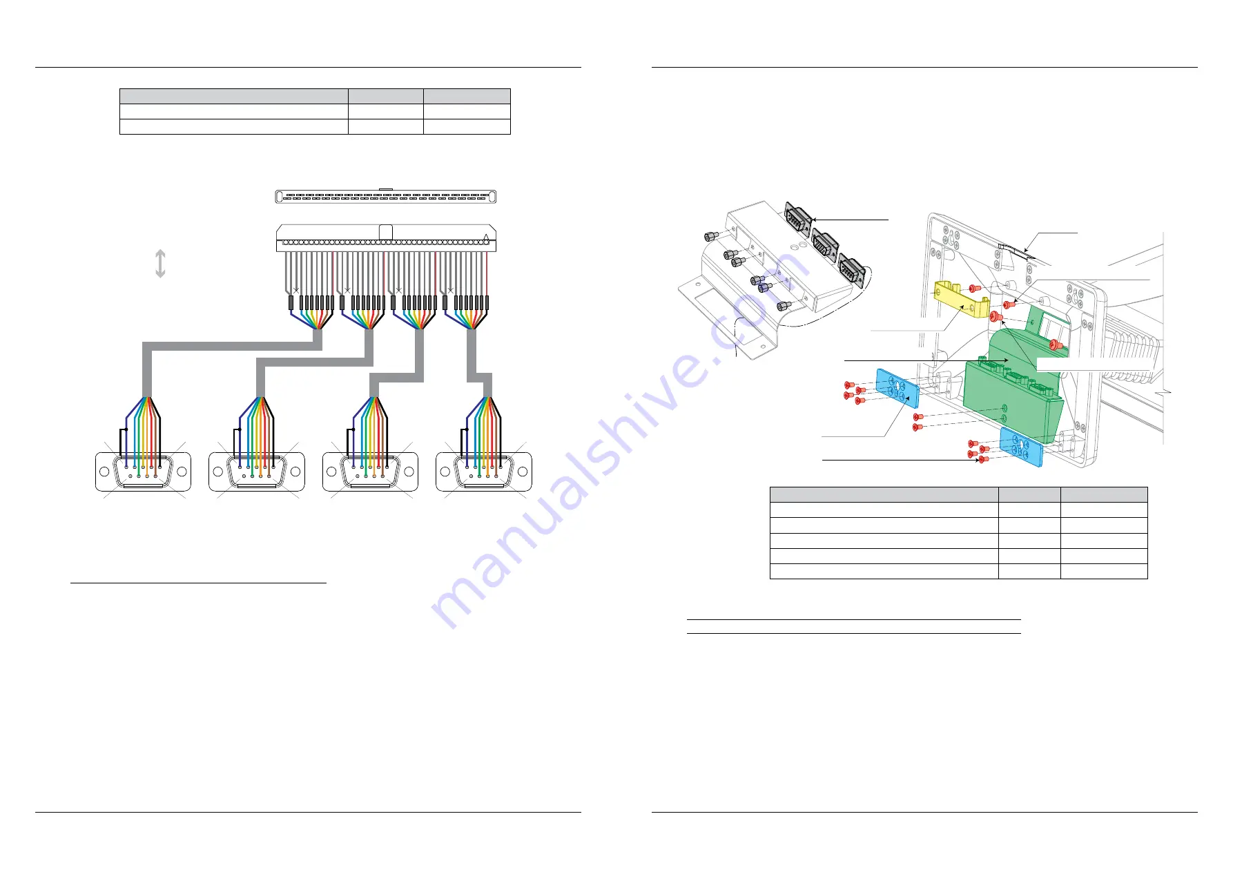
Figure 2.15.2. – COM ports interconnection for Tx execution

to COM conn. on Wafer

rear COM3-6 conn.

Rear view

1

5

6

9

Rear view

1

5

6

9

Rear view

1

5

6

9

Rear view

1

5

6

9

Top view, opened

Front view, closed

1

40

COM6

COM5

COM4

COM3


In this case are connectors lead out of device on own cables. Cables lenght depends on stand hight or 

following individual needs.

2.15.3. Installation of holder of extended connectors


Holder of extended connectors is metal bracket to fixation next connectors directly into leg of Uniq PC 

150. This solution retains all the original features of Uniq 150 included IP protection class and also provides 

compact option to extend the connectivity of other external devices.
 

Cable holder is in the Uniq 150 fitted as standard. If it was lack of cable holder width, is given a wider 

holder assembly process.
 

This holder is assigned only for COM connectors, but it could hold any type of D-SUB connector as VGA 

connector, etc. D-SUB connector could be arbitrarily combined.

1. We recommend to order a leg with wider gap for cables.

2. In case of whole leg replace is necessary to move all components of original leg to a new one, except of  the 

connectors cover and the longest metal strip on the front side of leg.

3. Fix connectors to extended connectors holder. Screws are included connectors.

4. Fix connectors holder to the leg using original screws of the longest metal strip and connectors cover. The screws 

remains of previous step. Connectors cables lead between holder and leg. Interconnection of cables is described in 

particular chapter.

5. Fix a new metal strips into the leg using screws remains of previous steps.

6. Fix connectors holder to the leg with screws referred in table. First screw the screws but do not tighten them. Then  

Skrutkami uvedenými v tabuľke prichytiť držiak káblov k nohe tak, že najprv naskrutkovať skrutky, ale nedoťahovať 

ich. Then set up the cable holder under the screws and then tighten the screws securely through the holes in the 

holder.

Note:  Follow the chapter Hinge replace for the leg replace. It is important proper cuff position because of IP 

protection class.

Figure 2.15.3. – Installation of holder of extended connectors

Metal cable holder

Holder of

extended connectors

wider gap

Cables position

connectors

and its screws

Metal strip of

ext. connectors

Screw M3 × 6 DIN965 conical

Screw M3 × 6 mm DIN7985A

Screw M3 × 4 mm DIN7985A

Needed to order

Quantity

Ord. code

Leg UniqPC Devlyx

1

P230180065000

Metal strip of leg 2.0 Devlyx/UniqPC

2

M051069

Metal cable holder Devlyx/UniqPC

1 *

M051068

Screw M3 × 6 mm DIN7985A

2 *

M250021

Extended connectors holder Devlyx v.01/UniqPC

1

M051067

* Plastic cable holder is standard, but it is possible to use wider metal cable holder.

2.16. Installation and interconnection of audio connector

1. Dismount and adjust connectors cover (cut the corner).

2. Cut the cable to half and move it out, through hinge and connectors module.

3. Solder audio connector on the outher end of the cable. Cover soldered places with tubing.

4. Fix connector to a audio connector holder.

5. The connectors cover with cut corner fix back to the leg. Audio connector cable must go through the cut corner of 

the cover and fix audio connector holder on the leg too.

6. Plug audio connector to mainboard to AUDIO1 connector.

Содержание Uniq 150

Страница 1: ...Uniq 150 Uniq 150 Service manual version 1 4 Elcom spolo nos s ru en m obmedzen m Pre ov...

Страница 2: ...s not undergone language proofreading This guide as well as any part of it may not be copied repro duced or otherwise circulated without the permission of the publisher All rights of the company Elcom...

Страница 3: ...luetooth and WiFi installation 30 2 13 1 Bluetooth installation 30 2 13 2 WiFi installation into hinge 31 2 13 3 WiFi installation into milled covers 32 2 14 Interconnection and installation of VGA po...

Страница 4: ...2 25 1 Replacement of AUO kit 50 2 25 2 Replacement of DLC display with eTurbotouch touch panel 51 2 25 3 Replacement of display with capacitive touch panel vandalproof 53 Note 54 2 26 LED replacement...

Страница 5: ...Elcom spolo nos s ru en m obmedzen m Pre ov 5 Service manual Uniq 150 1 General specification...

Страница 6: ...td WiFi Bluetooth 1 5 USB 1 4 RS 232 1 VGA audio PS2 VGA audio optional IrDA remote control USB touch panel only Data backup 2 5 HDD 160 GB old standard 2 5 HDD 320 GB new standard 2 5 HDD 500 GB opti...

Страница 7: ...Elcom spolo nos s ru en m obmedzen m Pre ov 7 Service manual Uniq 150 2 Structural part...

Страница 8: ...e Mounting process 1 Connect cables of the covers according to mainboard type display type and touch panel Description of interconnection is placed in the particular chapter Exact interconnection of t...

Страница 9: ...rofessional who are pro perly equipped for such an operation 2 2 Mainboard replace 2 2 1 N270 1 Release the screw of the Pico Power PCB the little one 2 Pico Power board is connected to mainboard with...

Страница 10: ...ively destruction of Uniq 150 Figure 2 2 2 D525 mainboard replace Heat material SARCON 50 GR HI 25 25 0 5 mm Heat material SARCON 100 GR HK 20 20 1 mm Mainboard Screw M3 4 mm DIN7985A Insulation pad P...

Страница 11: ...front panel display If another display type as DLC is used PCB invertor is not necessary Disconnect cables of PCB before its dismounting interconnection is described in particular chapter The PCB is c...

Страница 12: ...COM3 6 VGA audio mic slot for RAM CF1 Compact Flash CN4 miniPCI slot MB Wafer N270 TP AUO Figure 2 5 2 Interconnection for D525 and eTurbotouch MB Wafer D525 TP eTurbotouch 1 J1 RST_BTN USB1 PWR_BTN D...

Страница 13: ...v Uniq Skrutka M3 4 mm DIN7985A 2 7 Stand removal Division of Uniq 150 according to stand execution is described in chapter Hinge set 2 7 1 Nx executions Note After leg removal disconnect Uniq 150 fro...

Страница 14: ...al Service manual Uniq 150 Screw M3 4 mm DIN7985A Screw M4 10 mm DIN912 Connectors cover Leg Figure 2 7 2 Tx execution Hinge rear part Hinge front part Screw M5 16 mm DIN912 Tube Holder Uniq 150 Screw...

Страница 15: ...replace 1 It is necessary to release all Uniq 150 hinge in some cases It is possible to put out all hinge after open ing Uniq 150 leg and connectors removal just release four Allen screws 2 Pull out h...

Страница 16: ...X U Z Z P Y Y P X X U V V U Z Z P Y Y P X X Cuff Direct P Angled U P P U P P U U P P Stand Leg Lx Tube Holder TH L3 L3 L2 L1 L1 L3 TH TH TH L1 cables gap direction forward leg jambs direction forward...

Страница 17: ...2427 Reader cable must be tucked completly inside Figure 2 10 1 MS reader installation strips 4 4 102 4 4 102 Tx components adjustment Nx components adjustment Front cover strip left Front cover strip...

Страница 18: ...35 65 KM57 bottom cover Doublesided thick tape 9 20 mm USB RFID reader ID12 Box PS17 35 65 KM57 top cover RFID holder Doublesided tape Tesafix 4965 9 55 mm Screw M2 5 8 DIN965 ku e ov cca 150 2 5 4 S...

Страница 19: ...g 1 6 10 mm 4 M010003 Cable 8 wires 250 mm 28 AWG 2H 1 M200143 Tie EKB91N 2 3 M250009 Bluetooth USB key 1 M310015 USB extension cord AF AM 1 m 1 M200141 Consumes only half of cable and only in Tx exec...

Страница 20: ...GA port is connected to mainboard to connector VGA1 Uniq PC or to connector CN1 Uniq Display Owing to VGA connector installation for Nx execution is necessary to assembly extended connectors holder 2...

Страница 21: ...to COM connector It is necessary to install extended connector holder for Nx execution 2 15 1 Com ports interconnection for Nx execution 1 Dismount D SUB connector and solder it on cable 2 Mount D SUB...

Страница 22: ...and connectors cover The screws remains of previous step Connectors cables lead between holder and leg Interconnection of cables is described in particular chapter 5 Fix a new metal strips into the le...

Страница 23: ...thick tubing long at least 20 mm on 4 wires cable with PS2 connector 6 Solder both cables and soldered places cover with the thin tubing 7 With thick tubing cover all wires together 8 Plug the cable t...

Страница 24: ...t and seal all installed components during installation 1 As by standard VESA holder installation it is necessary to change strenghtened jumb of rear cover and therefore is necessary to dismount compl...

Страница 25: ...ube is reworked surely will be necessary to adjust cables In order to move a LAN and USB cables through the gland the cables must be cut close to the inner connector cut must be inside of device and t...

Страница 26: ...locker Note Plug cables to the connectors before placing Uniq 150 on the wall Lead the cables through cuts on the longest edges of the wall holder Figure 2 21 Installation of wall holder Wall holder S...

Страница 27: ...4 Put arresting part in rear display cover First put the lockers of arresting part marked with arrows into the locker holes also marked with arrows 5 Then fix arresting part to the rear display cover...

Страница 28: ...ver 1 Adjust rear Uniq PC 150 cover according to figure and dismount ED 5000 display 2 Cable move through hole in the Uniq 150 cover and through leg with rear display cover 3 Solder the cable with 5 p...

Страница 29: ...lay and the touch panel on the front cover via clips Note AUO display with touch panel is one integral part 3 Place the display in the front cover put the clips in and fix them with screws 4 Stick a n...

Страница 30: ...g the solution also facilitate work with silicone Time of silicone solidification is about 24 hours Note We recommend to entrust the touch panel installation for aesthetic reasons to Elcom professiona...

Страница 31: ...2801800007 Touchpanel resistive gray frame white single TL with display P2801800008 Touchpanel resistive gray frame black multi TL with display 2 26 LED replacement and interconnection 2 26 1 Replacem...

Страница 32: ...pull it out with sufficient of strenght Fix it again with drop of Pattex There is a resistor 220R 0 6W on the LED diode anode to reduce the voltage Note Diode must be installed so that no water can se...

Страница 33: ...7 8 XC2 GND 1 2 3 4 2417SJ 05 01 5 XC1 1 2 3 4 2417SJ 05 01 5 XC3 Ord code Description Position PC MON M190210 Connector Neltron 2417SJ 05 01 XC1 1 0 M190209 Connector Neltron 2208R 08G XC2 1 0 M1902...

Страница 34: ...nF 16V MLCC 0603 X7R C1 C4 C12 3 M120049 Cond 10uF 16V Tantal case B C2 1 M120154 Cond 10uF 25V 1206 X7R PAN C3 C15 C16 C18 4 M120086 Cond 1nF 50V 0603 MLCC X7R C5 0 M120180 Cond 100uF 6 3V 1210 X5R C...

Страница 35: ...B key and press ENTER c After choosing boot device the Elcom service application starts and displays main menu 3 Choose option 2 Recovery partition with OS images installation and press ENTER The choo...

Страница 36: ...Choose USB device with test application from displayed list and confirm with ENTER 4 Run Unitest application by icon on desktop Execute tests of all installed devices according to description below No...

Страница 37: ...Play recorded data at bottom side Check if play options allow playing sound on speakers and tap on Play button The recorded voice should sound from speakers If not there is problem with microphone Not...

Страница 38: ...test application ii Choose COM port with registred RFID reader from the list in upper side of window Scan RFID tag The text read from tag must appear in the window m Test of magnethic card reader RFID...

Страница 39: ...finger or pointer nib the most accurate to the center of blinking spot and hold while blinking spot appears on the other place Note Note that touch point is center of all subjects touch the panel at t...

Страница 40: ...st Vertical Lines 10 Horizontal Lines 10 Vertical Tolerance 1 0 Horizontal Tolerance 1 0 4 Make sure that no mouse or other pointer device is connected to the UniqPC except the touch panel Tap on Line...

Страница 41: ...en starting follow next edge Tester accuracy is very important during the calibration 5 When all the edges is passed press Next button 6 The 49 points calibration appears after saving previous calibra...

Отзывы: