


Euro-500TX Handy
© Elcom, s. r. o.
Service manual
14
Euro-500TX Handy
© Elcom, s. r. o.
Service manual
15
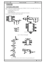
2.2.2 Memory circuits
The memory used by the microcontroller is divided into the two parts:
• programme memory
• data memory
The EPROM memory with the capacity of 256 kB serves as the programme memory. The data memory is
built on the static RAM memory (68C1000, 66C1024) and is expandable to 512 kB. The programme memory
(EPROM) is activated using the CS0 signal and the data memory (SRAM) is activated using the CS1 signal.
The ECR Euro-500TX handy uses
the ultra low power input memory
circuits that allow the lower power
supply demands and significantly
prolongs the backup of memory data
using the backup accumulator. The
exchange of said memory circuits
for other types with same capacity
can result in worse performance of
memory operations, increase of the
bus interference, and the memory
back-up time is shorter. It is recom-
mended to use only manufacturer
approved memory circuits.
In order to preserve the data in RAM
memory while the ECR is off, the
RAM memory is backed up from the
reserve accumulator.
Note: The chapter 4.7 describes how
to expand ECR memory to 512 kB.
Pin #.
Signature
Type
Signal description
80
P-LOW
I
scanning voltage value of internal connecting accumulator
81
PS1
I
scanning paper ribbon presence
82
PS2
I
scanning paper ribbon presence
83
HS
I
scanning printer head position
84
DRAWER
O
control signal for drawer opening
85
BUZZER
O
buzzer control
86
GND
I
0 V power supply
87
RDKEYB
O
signal for reading keyboard and JP4 - JP6 jumper condition
88
RW1
I
scanning keyboard
89
CS2
O
current time circuit activation
90
CS1
O
RAM memory activation
91
CS0x
O
program memory activation
92
GND
I
0 V power supply
93
PR-SEL
O
activation of circuit for production of STB1 – STB4, W-MOT and PLATCH
signals
94
PR-SET
O
control output for number of check bits written in one cycle to fast print circuit
95
A
O
1. phase of printer stepping motor
96
B
O
2. phase of printer stepping motor
97
SAVEPWR
O
signal of switching between normal and saving mode
98
EN
O
activation signal of stepping motor drivers
99
CS4
O
signal of data recording to circuit for production of STB1 – STB4, WMOT and
PLATCH signals
100
NC
NC
Tab. 2.1 Description of the E-500TXN microcontroller signals (cntd.)
A0
12
A1
11
A2
10
A3
9
A4
8
A5
7
A6
6
A7
5
A8
27
A9
26
A10
23
A11
25
A12
4
CS1
22
A17
30
WE
29
OE
24
D0
13
D1
14
D2
15
D3
17
D4
18
D5
19
D6
20
D7
21
A13
28
A14
3
A15
31
A16
2
A18
1
U2
KM681000A
A0
A1
A2
A3
A4
A5
A6
A7
A8
A9
A10
A11
A12
A13
A14
A15
A16
S17
A18
D0
D1
D2
D3
D4
D5
D6
D7
CS1
RD
HWR
R25
0R(opt. 4000)
A17
S17
A0
12
A1
11
A2
10
A3
9
A4
8
A5
7
A6
6
A7
5
A8
27
A9
26
A10
23
A11
25
A12
4
A13
28
A14
29
A15
3
CE
22
OE
24
DQ0
13
DQ1
14
DQ2
15
DQ3
17
DQ4
18
DQ5
19
DQ6
20
DQ7
21
A16
2
A17
30
VPP
1
PGM
31
U3
Socket
D0
D1
D2
D3
D4
D5
D6
D7
A0
A1
A2
A3
A4
A5
A6
A7
A8
A9
A10
A11
A12
A13
A14
A15
A16
A17
VCC
CS0
RD
R27
10k
VRAM
CS1
R26
10k
VRAM
Fig. 2.9 Memory connexion


