


ELKM43
CONTROLLER AND
MINI-PROGRAMMER
Quick guide
ELKM43-GB-06-05-B
EL.CO. S.r.l.
Via Lago di Molveno, 20 - 36015 Schio (VI)
ITALY
Tel.: +39 0445 661722 - Fax: +39 0445 661792
www.elco-italy.com
e-mail: [email protected]
Preface
m
This manual contains the information necessary for
the product to be installed correctly and also in-
structions for its maintenance and use; we therefore
recommend that the utmost attention is paid to the
following instructions and to save it.
This document is the exclusive property of eL.cO. S.r.l.
which forbids any reproduction and divulgation, even
partially, of the document, unless expressly authori-
zed. eL.cO. S.r.l. reserves the right to make any formal
or functional changes at any moment and without
notice.
eL.cO. S.r.l. and its legal representatives do not assume
any responsibility for any damage to people, things or
animals deriving from violation, wrong or improper
use or in any case not in compliance with the instru-
ment features.
m
Whenever a failure or a malfunction of the control
device may cause dangerous situations for persons,
thing or animals, please remember that the plant
has to be equipped with additional safety devices.
1. dIMeNSIONS aNd cuT-OuT (mm)
controller with non removable terminals
48
48
48
11
14
Panel cut-out
65 mm min.
45
+0.6
mm
45
+0.6
mm
65 mm min.
Mounting requirements
This instrument is intended for permanent installa-
tion, for indoor use only, in an electrical panel which
encloses the rear housing, exposed terminals and
wiring on the back. Select a mounting location having
the following characteristics:
1. It should be easily accessible;
2. There is minimum vibrations and no impact;
3. There are no corrosive gases;
4. There are no water or other fluids (i.e. condensation);
5. The ambient temperature is in accordance with the
operative temperature (0... 50°c);
6. The relative humidity is in accordance with the
instrument specifications (20... 85%);
The instrument can be mounted on panel with a
maximum thickness of 15 mm.
When the maximum front protection (IP65) is desired,
the optional gasket must be mounted.
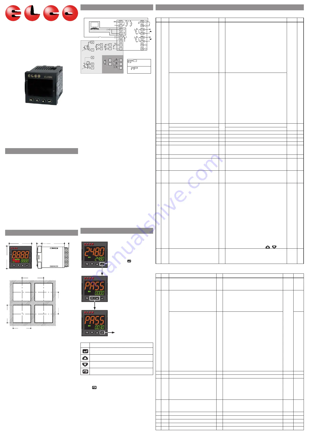
2. eLecTrIcaL cONNecTIONS
eLecTrIcaL cONNecTIONS
RS485
Thermo-
couple
DI1
OP3
OP2
OP1
OP4
(note)
DI2 (note)
Analogue input
mV, V
mA
12 VDC
(note)
PV
4... 20 mA
3 wire transmitter
12 VDC
(note)
PV
Pt100
Pt1000/NTC/PTC
4... 20 mA
2 wire transmitter
Neutral
Line
Power
supply
Terminals
Pin:
q
1.4 mm max. (0.055 in.)
Stropped wire: L: 5.5 mm (0.21 in.)
L
Note: Terminal 4 can be programmed as:
- digital Input (dI2) connecting a free of voltage
contact between terminals 4 and 16;
- 0... 12 V SSr drive Output (OP4) connecting the load
between terminals 4 and 16;
- 12 Vdc (20 ma) transmitter power supply connect-
ing the 2 wire transmitter between terminals 4
and 1; for 3 wire transmitter connect terminal
4 to transmitter power supply input and termi-
nal 1 and 2 to transmitter signal output.
Power supply voltage: 100... 240 Vac/20... 30 Vdc/
18... 28 Vac/24... 240Vac/dc;
Out1 relay: 4 (4) a/250 Vac, SPST;
Out2, 3 relay: 2 (1) a/250 Vac, SPST Na (*) ;
Out1, 2, 3 SSr: 10 Vdc/15 ma;
Linear Out1: 0/4... 20 ma, 0/2... 10 V;
Out4 SSr:
12 Vdc/20 ma.
* for
eLKM43 servodrive models both Out2 and Out3
are to be selected as “M” in configuration code;
Out2: open, Out3: close.
General notes about wiring
1. Safety regulations require a line switch marked as
instrument disconnecting device. This switch must
be easily reachable by the operator;
2. do not run input wires together with power cables;
3. external components (like zener barriers, etc.) con-
nected between sensor and input terminals may cause
errors in measurement due to excessive and/or not
balanced line resistance or possible leakage currents;
4. When a shielded cable is used, it should be con-
nected at one point only;
5. Pay attention to the line resistance, a high line
resistance may cause measurement errors.
6. To avoid electrical shocks, connect power line at last;
7. Before connecting the instrument to the power
line, make sure that line voltage is equal to the
voltage shown on the identification label;
8. The power supply input is NOT fuse protected.
Please, provide an external fuse T type 1a, 250 V.
3. cONfIGuraTION PrOcedureS
Setting the parameters
Press the key
for 3 seconds
Access to
parameters
Insert
password
(default: 30)
PV
AT
PV
AT
PV
AT
Key
editing Mode
confirm and go to Next parameter
Increase the displayed value or select the next element
decrease the displayed value or select the previous element
exit from Operator commands/Parameter setting/configuration
How to exit the “configuration mode”
To exit from the configuration mode,
press the
key for 3 seconds.
code configuration procedure
for eLKM43 version (without timer and programmer) a
simplified code configuration method is available. Only
essential functions can be set up with code configura-
tion procedure. See the “engineering user Manual” for
more details.
4. LIST Of THe ParaMeTerS (
pAss
: 30)
]
inP Group - Main and auxiliary input configuration
no. Par.
description
dec.
Values
default Notes
SenS
Model c
J
Tc J
(-50... +1000°c/-58... +1832°f);
craL Tc K
(-50... +1370°c/-58... +2498°f);
S
Tc S
(-50... 1760°c/-58... +3200°f);
r
Tc r
(-50... +1760°c/-58... +3200);
t
Tc T
(-70... +400°c/-94... +752°f);
Ir.J exergen IrS J (-46... +785°c/-50... +1445°f);
Ir.ca exergen IrS K (-46... +785°c/-50... +1445°f);
Pt1 rTd Pt 100 (-200... +850°c/-328... +1562°f);
Pt10 rTd Pt 1000 (-200... +850°c/-328... +1562°f);
0.60 0... 60 mV linear;
12.60
12... 60 mV linear;
0.20 0... 20 ma linear;
4.20 4... 20 ma linear;
0.5 0... 5 V linear;
1.5 1... 5 V linear;
0.10 0... 10 V linear;
2.10 2... 10 V linear.
J
Model e
J
Tc J
(-50... +1000°c/-58... +1832°f);
craL Tc K
(-50... +1370°c/-58... +2498°f);
S
Tc S
(-50... 1760°c/-58... +3200°f);
r
Tc r
(-50... +1760°c/-58... +3200);
t
Tc T
(-70... +400°c/-94... +752°f);
Ir.J exergen IrS J (-46... +785°c/-50... +1445°f);
Ir.ca exergen IrS K (-46... +785°c/-50... +1445°f);
Ptc PTc KTY81-121 (-55... +150°c/-67... +302°f);
ntc NTc 103-aT2 (-50... +110°c/-58... +230°f);
0.60 0... 60 mV linear;
12.60
12... 60 mV linear;
0.20 0... 20 ma linear;
4.20 4... 20 ma linear;
0.5 0... 5 V linear;
1.5 1... 5 V linear;
0.10 0... 10 V linear;
2.10 2... 10 V linear.
2
dp
decimal Point Position (linear inputs)
0
0... 3
0
decimal Point Position (non linear inputs)
0/1
3
SSc Initial scale read-out for linear inputs
dp -1999... 9999
0
4
fSc
full Scale readout for linear inputs
dp -1999... 9999
1000
5
unit engineer unit
°c/°f
°c
6
fil
digital filter on the measured value
1
0 (= Off)... 20.0 s
1.0
7
ine
Sensor error used to enable the safety output
value
or
Over range;
ur
under range;
our
Over and under range.
our
8
oPe Safety output value (% of the output)
-100... 100
0
9
IO4.f I/O 4 function
on
Output used as PWS for TX;
out4 Output 4 (digital output 4);
dG2c digital input 2 driven by contact;
dG2u digital input 2 driven by voltage.
out4
9
IO4.f I/O 4 function
on
Output used as PWS for TX;
out4 Output 4 (digital output 4);
dG2c digital input 2 driven by contact;
dG2u digital input 2 driven by voltage.
out4
10 dif1 digital Input 1 function
off Not used;
1
alarm reset;
2
alarm acknowledge (acK);
3
Hold of the measured value;
4
Stand by mode;
5
Manual mode;
6
Heat with SP1 and cooL with SP2;
7
Timer ruN/Hold/reset;
8
Timer run;
9
Timer reset;
10
Timer run/Hold;
11
Timer run/reset;
12
Timer run/reset with lock;
13
Program Start;
14
Program reset;
15
Program Hold;
16
Program run/Hold;
17
Program run/reset;
18
Sequential SP selection;
19
SP1 - SP2 selection;
20
SP1... SP4 binary selection;
21
digital inputs in parallel to
/
keys.
off
12 di.a digital input action (dI2 only if configured)
0
dI1 direct action, dI2 (if configured) direct action;
1
dI1 inverse action, dI2 (if configured) direct action;
2
dI1 direct action, dI2 (if configured) inverse action;
3 dI1 inverse action, dI2 (if configured) inverse
action.
0
]
Out group - Output parameters
no. Par.
description
dec.
Values
default Notes
13 o1t
Output 1 type (when Out 1 is a linear
output)
0-20 0... 20 ma;
4-20 4... 20 ma;
0-10 0... 10 V;
2-10 2... 10 V.
0-20
14 o1f
Out 1 function (when Out 1 is a linear
output)
0
None Output not used;
H.reG Heating output;
c.reG cooling output;
r.inP Measure retransmission;
r.err
error (SP - PV) retransmission;
r.SP
Set point retransmission;
r.Ser Serial value retransmission.
H.reG
Out 1 function (when Out1 is a digital
output)
0
None Output not used;
H.reG Heating output;
c.reG cooling output;
aL
alarm output;
t.out Timer output;
t.Hof Timer out -Off in hold;
P.end Program end indicator;
P.HLd Program hold indicator;
P.uit
Program wait indicator;
P.run Program run indicator;
P.et1 Program event 1;
P.et2 Program event 2;
or.bo Out of range or burn out indicator;
P.faL Power failure indicator;
bo.Pf Out of range/burn out/Power failure indicator;
St.bY Stand by status indicator;
dif.1
The output repeats the digital input 1 status;
dif.2
The output repeats the digital input 2 status;
on
Out 1 always ON;
riSP
Inspection request.
15 ao1L Initial scale for the analog retransmission dP -1999 ... ao1H
-1999
16 ao1H full scale for the analog retransmission dP ao1L ... 9999
9999
17 o1aL alarms linked up with the out 1
0
0... 63:
+1
alarm 1;
+2
alarm 2;
+4
alarm 3;
+8 Loop break alarm;
+16 Sensor Break;
+32 Overload on output 4.
1
18 o1ac Out 1 action
0
dir
direct action;
reu
reverse action;
dir.r
direct with reversed Led;
reu.r reverse with reversed Led.
dir
19 o2f Out 2 function
0
See O1f - Out 1 function (digital output)
aL
20 o2aL alarms linked up with the out 2
0
See O1aL - alarms linked up with the out 1
1
21 o2ac Out 2 action
0
See O1ac - Out 1 action
dir
22 o3f Out 3 function
0
See O1f - Out 1 function (digital output)
aL
23 o3aL alarms linked up with the out 3
0
See O1aL - alarms linked up with the out 1
2