


Application manual
Air quality multisensor and regulator EK-ES2-TP
Release 1.0 - Updated: 14/02/2020
Application Manual
© EKINEX S.p.A. - All rights reserved
Page 56
a radiator system that has a fan-coil as auxiliary stage for heating; the same fan coil unit functions as
main stage for cooling.
In these cases with the configuration adopted, the following steps are necessary:
1.
Settings
Thermostat function = both heating and cooling. This configuration enables both folders
(heating and cooling)
2.
Heating
Heating type = floor radiant panels or ceiling radiant panels
3.
Heating
Command communication object = separated (if unique is choosen, the parameter Cooling
Cooling type does not appear)
4.
Heating
Auxiliary heating = enabled
5.
Auxiliary heating
Communication object = separated
6.
Heating
Ventilation for auxiliary heating = enabled
7.
Cooling
Cooling type = fancoils
Important!
If the fan-coil system has a 2-pipe hydraulic configuration, the objects Auxiliary heating
output command (1 bit) and Cooling out command (1 bit) have to be set in logical OR in the actuator
for controlling the fan-coil which in this case is unique.
An alternative solution that avoids the setting of a logic OR can be realized by configuring a main
stage for heating and cooling with radiant panels through separate valves and an auxiliary stage
for heating and cooling fan coil through combined valves. The offset of the auxialiary stage for
cooling is set to the value 0 (zero); this corresponds to a configuration for main stage. The object
Cooling out command (1 byte) is not connected so that the radiant panel system works only for
heating.
7.7.4.5
Remote fan speed modification
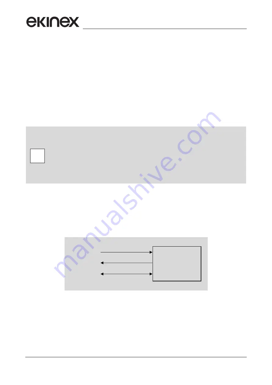
The communication objects shown in figure allow to monitor actiual fan speed forced automatically (A) by the
temperature controller or set locally by the user when interacting with the LCD display and the touch buttons
of the room thermostat. The communication objects (from now on: C.O.) also allow to perform the same
modifications remotely, for example from a supervisor software.
Picture 10
The C.O.
67 – Fan speed
allows to evaluate the actual fan speed; the C.O. 70
– Fan manual active status
contains the information about automatic (=0, not active) or manual (=1, active) operating mode. By modifying
the C.O. 68
– Fan manual speed
, the fan automatically switches to the setpoint speed; to return to automatic
mode (A), the supervisor must exit from manual mode by modifying the C.O. 70
– Fan manual active status
(=0, not active).
Accepted values for C.O.s 67 and 68 depend on the number of speeds set in ETS.
i
67
– Fan speed [5.010 counter pulses]
70
– Fan manual active status [1.011 state]
68
– Fan manual speed [5.010 counter pulses]