background image

28

Chapter 5  Reference 

5-  Preset Timing

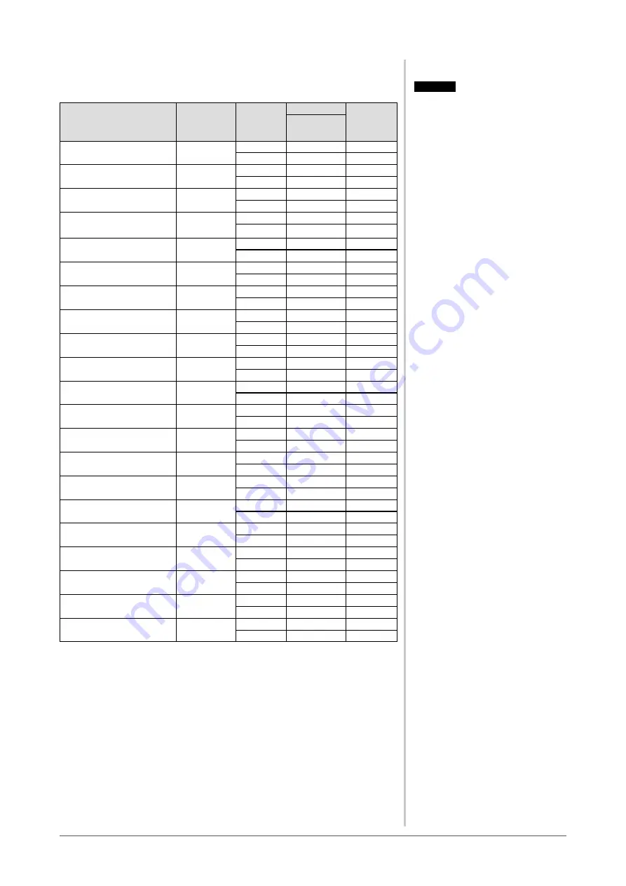
The following table shows factory preset video timing.

Mode

Dot clock

Frequency

Polarity

Horizontal: kHz
Vertical: Hz

VGA 640×480@60Hz

25.2 MHz

Horizontal

31.47

Negative

Vertical

59.94

Negative

VGA 720×400@70Hz

28.3 MHz

Horizontal

31.47

Negative

Vertical

70.09

Positive

Macintosh 640×
480@67Hz

30.2 MHz

Horizontal

35

Negative

Vertical

66.67

Negative

Macintosh 832×
624@75Hz

57.3 MHz

Horizontal

49.73

Negative

Vertical

74.55

Negative

Macintosh 1152×
870@75Hz

100.0 MHz

Horizontal

68.68

Negative

Vertical

75.06

Negative

Macintosh 1280×
960@75Hz

126.2 MHz

Horizontal

74.76

Positive

Vertical

74.76

Positive

PC-9801 640×400@56Hz

21.0MHz

Horizontal

24.83

Negative

Vertical

56.42

Negative

PC-9821 640×400@70Hz

25.2 MHz

Horizontal

31.5

Negative

Vertical

70.15

Negative

VESA 640×480@72Hz

31.5 MHz

Horizontal

37.86

Negative

Vertical

72.81

Negative

VESA 640×480@75Hz

31.5 MHz

Horizontal

37.5

Negative

Vertical

75

Negative

VESA 800×600@56Hz

36.0 MHz

Horizontal

35.16

Positive

Vertical

56.25

Positive

VESA 800×600@60Hz

40.0 MHz

Horizontal

37.88

Positive

Vertical

60.32

Positive

VESA 800×600@72Hz

50.0 MHz

Horizontal

48.08

Positive

Vertical

72.19

Positive

VESA 800×600@75Hz

49.5 MHz

Horizontal

46.88

Positive

Vertical

75

Positive

VESA 1024×768@60Hz

65.0 MHz

Horizontal

48.36

Negative

Vertical

60

Negative

VESA 1024×768@70Hz

75.0 MHz

Horizontal

56.48

Negative

Vertical

70.07

Negative

VESA 1024×768@75Hz

78.8 MHz

Horizontal

60.02

Positive

Vertical

75.03

Positive

VESA 1152×864@75Hz

108.0 MHz

Horizontal

67.5

Positive

Vertical

75

Positive

VESA 1280×960@60Hz

108.0 MHz

Horizontal

60

Positive

Vertical

60

Positive

VESA 1280×1024@60Hz

108.0 MHz

Horizontal

63.98

Positive

Vertical

60.02

Positive

VESA 1280×1024@75Hz

135.0 MHz

Horizontal

79.98

Positive

Vertical

75.03

Positive

Attention

•  Display position may be deviated 

depending on the PC connected, 

which may require screen adjustment 

using Adjustment menu.

•  If a signal other than those listed in 

the table is input, adjust the screen 

using the Adjustment menu. However, 

screen display may still be incorrect 
even after the adjustment.

•  When interlace signals are used, the 

screen cannot be displayed correctly 
even after screen adjustment using the 
Adjustment menu.

Содержание FlexScan S1961

Страница 1: ...nt 2 3 Color Adjustment 2 4 Off Timer Settings 2 5 Power Indicator EIZO Logo Display Setting 2 6 Locking Buttons 2 7 Setting Adjustment menu Display 2 8 Viewing Information Setting Language 2 9 Settin...

Страница 2: ...mation confidential unless prior arrangements are made pursuant to EIZO NANAO CORPORATION s receipt of said information Although every effort has been made to ensure that this manual provides up to da...

Страница 3: ...mpting to use a malfunctioning unit may result in fire electric shock or equipment damage Do not open the cabinet or modify the unit Opening the cabinet or modifying the unit may result in fire electr...

Страница 4: ...not place near heat generating devices or a humidifier To avoid danger of suffocation keep the plastic packing bags away from babies and children Use the enclosed power cord and connect to the standar...

Страница 5: ...ecome unattached which may result in injury or equipment damage When the unit is dropped please ask your dealer for advice Do not continue using a damaged unit Using a damaged unit may result in fire...

Страница 6: ...it laid down or upside down Blocking the ventilation slots prevents proper airflow and may result in fire electric shock or equipment damage Do not touch the plug with wet hands Doing so may result in...

Страница 7: ...e is dark or black If pressure is repeatedly applied to the screen it may deteriorate or damage your LCD panel Leave the screen white to decrease the prints Do not scratch or press on the panel with a...

Страница 8: ...Setting 16 To turn off the Power indicator while a screen is displayed Power Indicator Setting 16 To display EIZO logo EIZO Logo Hiding Function 16 2 6 Locking Buttons 17 To lock operation Adjustment...

Страница 9: ...he EIZO LCD Utility Disk Ultra slim bezel 1 2 Buttons and Indicators Buttons Adjustment menu ScreenManager 1 Sensor BrightRegulator 2a Volume control button turn down 1 2b Brightness control button tu...

Страница 10: ...ic Adjustment Screen to adjust flickering and position see page 11 Range to adjust color gradation automatically see page 13 Color Adjustment Advanced Adjustment Adjustment menu Brightness Temperature...

Страница 11: ...ion to change Adjustment menu settings see page 17 Power Indicator Setting Power Indicator Setting to turn off the indicator while the screen is displayed see page 18 BrightRegulator setting BrightReg...

Страница 12: ...asy adjustments of the monitor screen following adjustment patterns and procedures on the screen ScreenManager Pro for LCD for Windows application software A utility software program to control monito...

Страница 13: ...orm the adjustment following the procedure below When the screen is displayed correctly go to step 4 Range Adjustment Advanced Adjustment 2 Run the Screen Adjustment Program Load the EIZO LCD Utility...

Страница 14: ...To remove flickering or blurring Phase 1 Choose Phase from the Screen menu and press The Phase menu appears 2 Adjust the phase with or and press The adjustment is completed To correct screen position...

Страница 15: ...displayed by adjusting the signal output level 1 Choose Range from the Auto Adjustment menu and press 2 Choose Execute and press 3 Color gradation is adjusted correctly by the auto adjustment functio...

Страница 16: ...tness etc 1 Choose Color Mode from the Color menu 2 Choose Custom sRGB or Text with or and press FineContrast Mode An appropriate display mode is selectable out of three modes Mode Purpose Custom Avai...

Страница 17: ...ues shown in percentage are available only as reference The Temperature setting invalidates this setting The Gain setting varies with color temperature Reset To reset the color settings of the selecte...

Страница 18: ...is completed Resumption Procedure Press 2 5 Power Indicator EIZO Logo Display Setting To turn off the Power indicator while a screen is displayed Power Indicator Setting This function enables to turn...

Страница 19: ...screen is displayed with the adjustment lock Unlocking 1 Press to turn off the unit 2 Press again while pressing The screen is displayed with the adjustment lock released 2 7 Setting Adjustment menu...

Страница 20: ...age setting is completed 2 9 Setting BrightRegulator BrightRegulator to set Enable or Disable for BrightRegulator 1 Choose Others from the Adjustment menu and press 2 Choose BrightRegulator from the O...

Страница 21: ...Input signal switches each time is pressed When the signal is switched the active signal type Analog or Digital appears at the top right corner of the screen for two seconds DVI D connector D sub mini...

Страница 22: ...e is connected properly The message below shows that the input signal is out of the specified frequency range Such signal frequency is displayed in red Example Select an appropriate display mode using...

Страница 23: ...function 11 The auto adjustment function does not work correctly This function does not work when digital signal is input This function works correctly when an image is fully displayed over the Windo...

Страница 24: ...user s manual of the arm or stand Fixing screws M4 12mm 4 pcs Attention When attaching an arm or stand follow the instructions of their user s manual When using another manufacturer s arm or stand con...

Страница 25: ...ower saving Orange Resumption Procedure Operate the mouse or keyboard to resume the normal screen from the PC s power saving mode 5 3 Cleaning Clean the monitor periodically to keep the monitor clean...

Страница 26: ...with no line input connector connected Input Signal Connectors DVI D connector D sub mini 15 pin connector Analog Input Signal Sync H V Separate TTL positive negative Analog Input Signal Video Analog...

Страница 27: ...25 Chapter 5 Reference Main default settings factory settings BrightRegulator Disabled FineContrast Mode Custom Off Timer Disabled Language English Outside Dimensions unit mm inch...

Страница 28: ...22 TMDS Clock shield 7 DDC Data SDA 15 Ground return for 5V Hsync and Vsync 23 TMDS Clock 8 NC 16 Hot Plug Detect 24 TMDS Clock NC No Connection D sub mini 15 pin connector 5 1 3 4 2 8 7 6 9 10 12 13...

Страница 29: ...ng the light intensity volume passing through each color s filter Phase Phase means the sampling timing to convert the analog input signal to a digital signal Phase adjustment is made to adjust the ti...

Страница 30: ...5 Positive VESA 800 600 60Hz 40 0 MHz Horizontal 37 88 Positive Vertical 60 32 Positive VESA 800 600 72Hz 50 0 MHz Horizontal 48 08 Positive Vertical 72 19 Positive VESA 800 600 75Hz 49 5 MHz Horizont...

Страница 31: ...y Energy Energy saving mode after a certain time beneficial both for the user and environment Electrical safety Emissions Electromagnetic fields Noise emissions Ecology The products must be prepared f...

Страница 32: ...no guarantee that interference will not occur in a particular installation If this equipment does cause harmful interference to radio or television reception which can be determined by turning the equ...

Страница 33: ...da die H he der Bildschirmmitte ber dem Boden zwischen 135 150 cm betr gt d Der Standfu mu die M glichkeit zur Neigung des Bildschirmger tes besitzen max vorw rts 5 min nach hinten 5 e Der Standfu mu...

Страница 34: ...Switzerland All recycling information is placed in the SWICO s website http www swico ch Recycling Information f r Kunden in der Schweiz Alle Informationen zum Thema Recycling finden Sie auf der Homep...

Страница 35: ......

Отзывы: