9
Chapter1Introduction
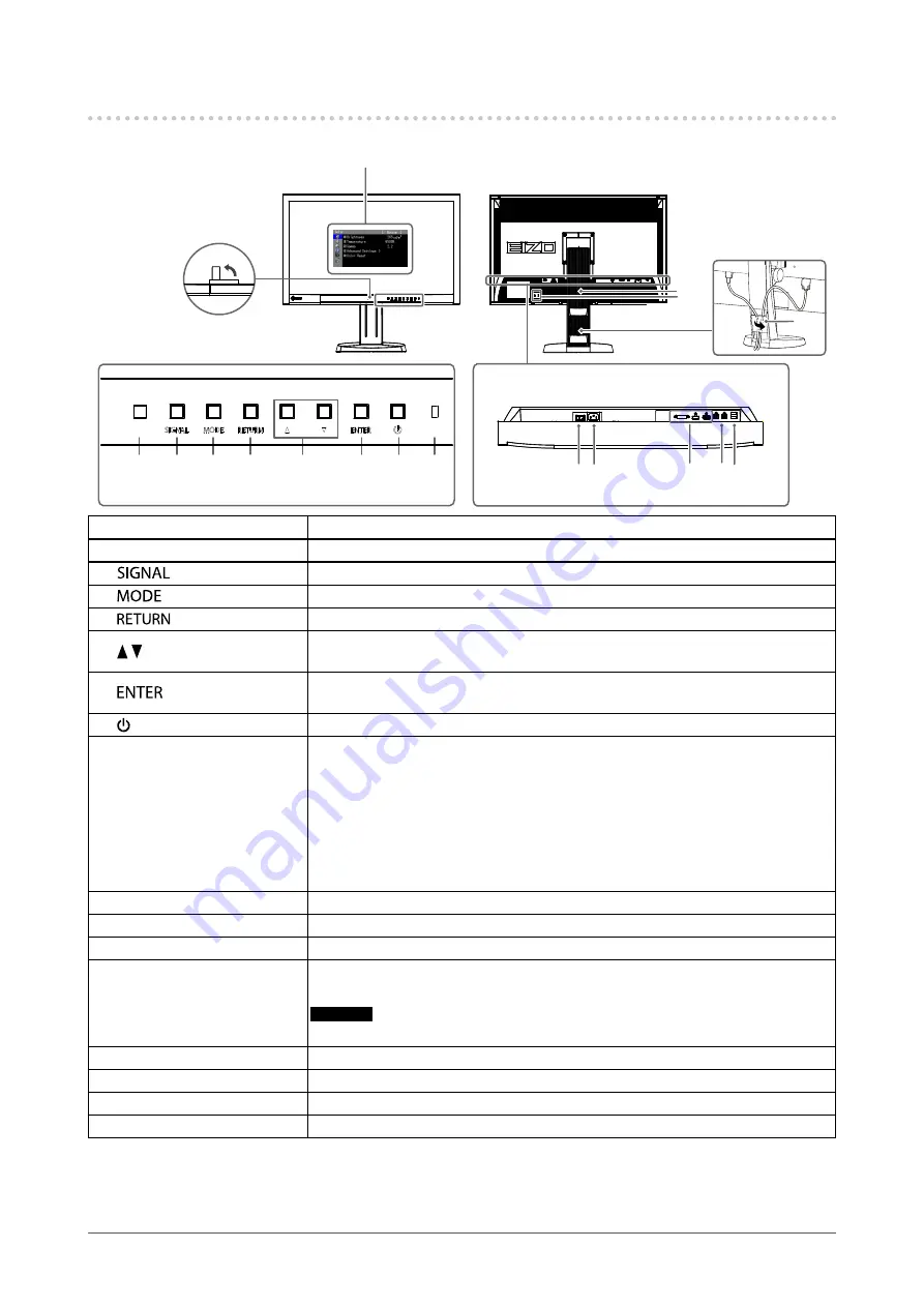
1-2. Controls and Functions
1
16
17
10 11
12 13 14
15
7
8
9
2
4
5
3
6
Adjustmentmenu
*1
1. Built-in calibration sensor
Executescalibrationforanindependentmonitor.SelfCalibrationfunction(
)
2. Ambient Light Sensor
Measuresambientlight.
3.
button
Switchesinputsignalsfordisplay(
“Toswitchamonginputsignals”(page49)
).
4.
button
ChangesColorMode(
).
5.
button
Cancelsthesetting/adjustmentandexitstheAdjustmentmenu.
6. buttons
• Providesthemenuselectionaswellastheadjustmentandsettingofafunction.
• DisplaystheBrightnessmenu(
“AdjustingBrightness”(page19)
).
7.
button
DisplaystheAdjustmentmenu,determinesanitemonthemenuscreen,andsaves
valuesadjusted(
).
8. button
Turnsthepoweronoroff.
9. Power Indicator
Indicatesthemonitor’soperationstatus.
Blue:
Operating
Flashingblue
(2timesforeach):
Inthefollowingcases,thisnotifiesthatdisplayre-correction
isrequired.
• WhenthetimerissetinColorNavigator(CALmode)
Orange:
Powersavingmode
OFF:
Mainpower/Poweroff
10. Main power switch
Turnsthemainpoweronoroff.
11. Power connector
Connectsthepowercord.
12. Input signal connectors
Left:DVI-Dconnector/Center:HDMIconnector/Right:DisplayPortconnector
13. USB upstream port
ConnectstheUSBcabletousethesoftwarethatneedsUSBconnection,ortouse
USBhubfunction(
“7-3.MakingUseofUSB(UniversalSerialBus)”(page50)
).
Attention
• By default, USB upstream port 1 is enabled. Connect the cable to USB upstream port 1 first.
14. USB downstream port
ConnectsaperipheralUSBdevice.
15. Stand
*2
Usedtoadjusttheheightandangleofthemonitorscreen.
16. Security lock slot
ComplieswithKensington’sMicroSaversecuritysystem.
17. Cable holder
Coversthemonitorcables.
*1 See
“1-4. Basic Operations and Functions” (page 11)
for how to use.
*2 An optional arm (or an optional stand) can be attached by removing the stand section (see
“7-1. Attaching the Optional Arm”
).


