manualshive.com logo in svg
background image

REPAIR  GUIDELINE 

Brush Cutter Attachment_BCA1200 

Version: 1 

Issue Date: 12/02/2016 

Содержание BCA1200

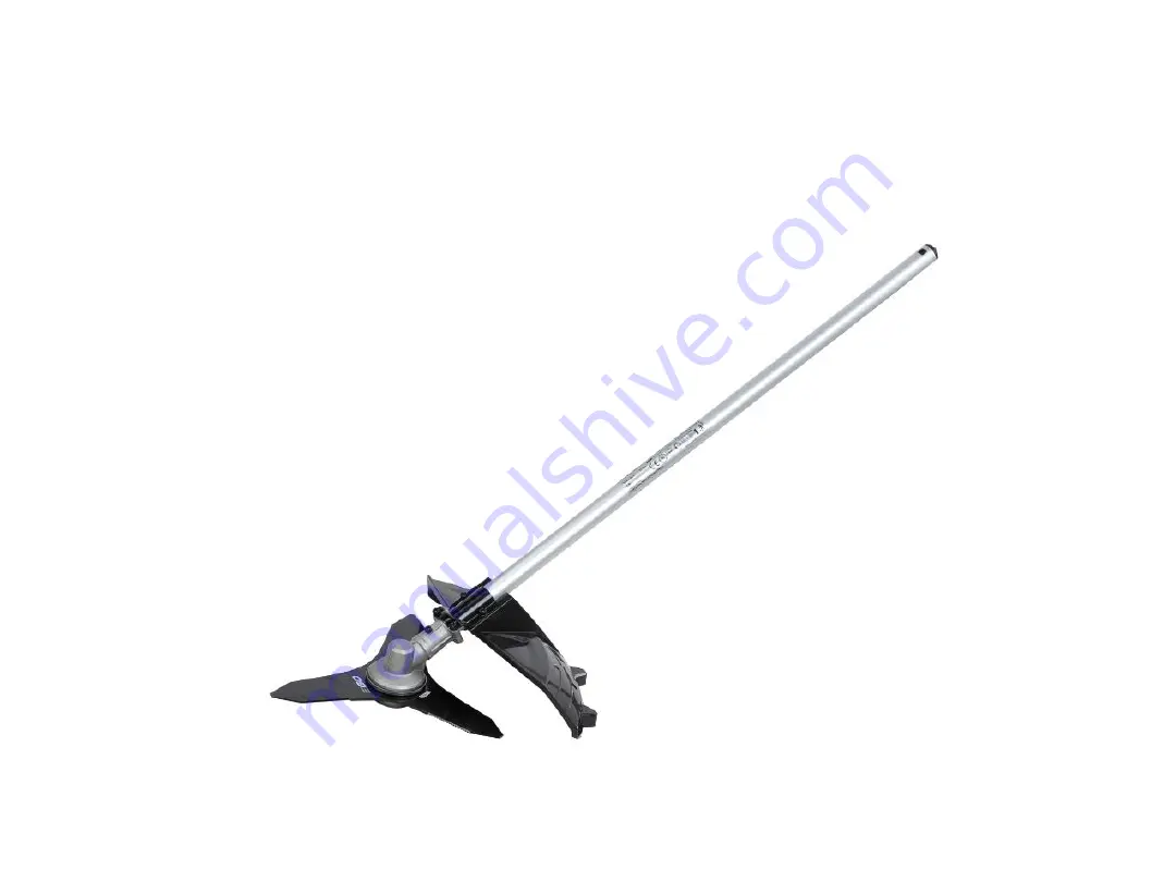
Страница 1: ...REPAIR GUIDELINE Brush Cutter Attachment_BCA1200 Version 1 Issue Date 12 02 2016...

Страница 2: ...Table of Contents 2 NO Contents Page 1 Troubleshooting 3 2 Tool list 4 3 Part 1 Replace the Blade and Gear Case 5 29...

Страница 3: ...se Fault Position Test Solution Blade worn Overload or wear and tear Blade Replace it with a new one Noise Lack of grease in gearbox Gear case Add grease Excessive vibration Unbalanced Eccentric blade...

Страница 4: ...Tool List For Repair 4 NO Tool List SPEC Remark 1 Socket wrench 14mm 2 Hex wrench 4mm...

Страница 5: ...5 Part 1 Replace the Blade and Gear Case...

Страница 6: ...1 Press the locking bar to remove the blade cover 6 Replace the Blade and Gear Case Press Locking bar...

Страница 7: ...mble the guard assembly if the guard assembly is broken replace it with a new one 7 Replace the Blade and Gear Case Description Part Number Qty Tapping screw 5620216003 1 Guard assembly 2824703001 1 T...

Страница 8: ...3 Rotate the blade to align the slot in the flange with the hole in the gear case 4 Insert the hex wrench into the aligned holes to act as a stabilizer 8 Replace the Blade and Gear Case...

Страница 9: ...5 Loosen the nut with multifunction wrench clockwise to remove the nut from the shaft 9 Replace the Blade and Gear Case Nut Description Part Number Qty Nut 5630292001 1...

Страница 10: ...Take the outer flange out of the shaft 7 Take the blade out of the shaft 10 Replace the Blade and Gear Case Outer flange Blade Description Part Number Qty Outer flange 3421864001 1 Blade 3706105001 1...

Страница 11: ...Take the shield out of the shaft 9 Take the inner flange out of the shaft 11 Replace the Blade and Gear Case Shield Inner flange Description Part Number Qty Shield 3706103001 1 Inner flange 3552509001...

Страница 12: ...10 Loosen 2 screws to remove the fixing board 12 Replace the Blade and Gear Case Fixing board Screw Description Part Number Qty Screw 5620216003 1 Fixing board 3705417001 1...

Страница 13: ...11 Loosen the screw to separate the gear case assembly from the connecting tube 12 If any part was broken or worn replace it with a new one 13 Replace the Blade and Gear Case Screw Gear case assembly...

Страница 14: ...13 Align the hole on the connecting tube with the hole on the gear case and then tighten them together with the screw 14 Replace the Blade and Gear Case Hole Hole...

Страница 15: ...14 Mount the fixing board onto the connecting tube and assemble them with screws 15 Replace the Blade and Gear Case...

Страница 16: ...15 Mount the inner flange onto the shaft 16 Mount the shield onto the shaft 16 Replace the Blade and Gear Case...

Страница 17: ...17 Mount the blade onto the shaft 18 Mount the outer flange onto the shaft 19 Mount the nut onto the shaft and pre tighten it anticlockwise 17 Replace the Blade and Gear Case...

Страница 18: ...lign the slot in the flange with the hole in the gear case 21 Insert the hex wrench into the aligned holes to act as a stabilizer 22 Tighten the nut anticlockwise with multi function wrench 18 Replace...

Страница 19: ...23 Align the holes on the fixing board with the holes on the connecting tube to assemble them with screws 19 Replace the Blade and Gear Case...

Страница 20: ...24 Mount the blade onto the blade cover and press the locking bar to assemble them 20 Replace the Blade and Gear Case...

Отзывы: