Eggtimer Quark
Assembly Manual
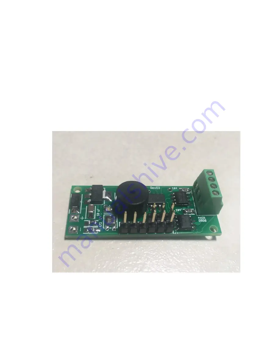
Board Rev D3
© 2021 Eggtimer Rocketry All Rights Reserved
Страница 1: ...Eggtimer Quark Assembly Manual Board Rev D3 2021 Eggtimer Rocketry All Rights Reserved...
Страница 2: ...t what went wrong so it doesn t happen again If your Eggtimer Quark does not work properly after assembly take a deep breath get out the magnifying glass and a good light and see if you have inadverte...
Страница 3: ...assembly but you should take the following precautions when using it or just about any chemical for that matter Do not eat or drink while using it Wash your hands after handling it Keep it in the prot...
Страница 4: ...If you do not have any experience soldering kits such as the Quark we recommend that you ask around chances are that somebody in your rocketry club would be more than happy to assist you for a small b...
Страница 5: ...to use it occasionally Weller makes a decent cheap 12W iron it s about 15 There is also a similar iron that s sold by ECG We like those but the copper tips seem to oxidize and corrode rather quickly...
Страница 6: ...s loupe or small 10x magnifier for inspecting the SMT solder joints ___ A well lighted place to work preferably with a wood or metal surface also preferably not carpeted ___ Some PAPER masking tape do...
Страница 7: ...oard with pre mounted barometric pressure sensor __ 1 ATTINY84A 20SU Processor 14 pin SOIC chip __ 1 NCP1117 33 3 3V voltage regulator SOT223 package __ 2 VN5E160S Driver Chips 8 pin SOIC chip __ 1 FM...
Страница 8: ...before you solder and that you make SURE that you have them pointed the right direction before soldering Like the old adage says Measure twice cut once If you solder a part onto the board incorrectly...
Страница 9: ...he part down to the board or clip the leads after you solder them To mount these parts 1 Lightly tin ONE pad 2 Hold the part in place with tweezers then heat up the tinned pad until the solder flows u...
Страница 10: ...esistor on the center of the pad Remove the soldering iron and let it cool for 5 seconds before you let go of the resistor __ Solder the left pad of the 104 resistor Check both solder joints with a 10...
Страница 11: ...er you will notice that there is a ST logo on the top left corner of the chip That is the Pin 1 mark which must align with the little box in the top left corner of the driver chip marking on the PC bo...
Страница 12: ...der on the chip s lead but miss the PC board pad a good solder joint should actually flow underneath the chip lead and bond the elbow of the lead to the pad ___ Now solder the remaining leads in the s...
Страница 13: ...esistor marked 104 on the right side of the board just below the driver chip that you just mounted ___ Solder the bottom 100K resistor in place in the same manner as the top one Mount the Bottom Drive...
Страница 14: ...ds then carefully remove the soldering iron and wait 5 seconds for the solder to cool ___ Carefully solder the lower right pad Check the pad with a 10x jeweler s loupe to make sure that the solder joi...
Страница 15: ...or chip on the board and hold it in place while heating up the previously tinned upper right pad Make sure that the chip is centered on all 14 pads then carefully remove the soldering iron and wait 5...
Страница 16: ...1 uF capacitor next to the processor ___ Solder the capacitor in place in the same manner as the resistors Note that the right pad is next to the upper right pad on the processor they are actually co...
Страница 17: ...1 uF capacitor that you soldered earlier this resistor does NOT connect to the nearby processor lead so if you get a solder bridge between the two you will need to remove the excess solder with some...
Страница 18: ...rs they re just to the left of the silver baro sensor and are marked 472 on the board ___ Tin the right pad of the top 4 7K resistor ___ Solder the top 4 7K resistor in place in the same manner as the...
Страница 19: ...4 7K resistors ___ Solder the 10 uF capacitor in place in the same manner as the other resistors capacitors ___ Locate the second 10 uF capacitor to the left of the processor and the 1 uF capacitor __...
Страница 20: ...e is one large pad on the right side and three smaller pads on the left side ___ Lightly tin the center pad of the three pads on the left ___ While heating up the tinned pad hold the voltage regulator...
Страница 21: ...left side of the board and has a mark with an arrow and a line at one end ___ Tin the right pad of the diode ___ If you look at the diode you ll see that the package has a stripe at one end This stri...
Страница 22: ...want to have to remove the buzzer it s not all that easy ___ With a 10x jeweler s loupe check the solder joints on ___ The 10K 103 resistor ___ The 1 uF capacitor to the left of the processor ___ The...
Страница 23: ...e tape Mount the Terminal Block optional Optionally you can install the 4 pin terminal block for your deployment wiring Given the relatively low cost of a Quark we generally recommend that you hardwir...
Страница 24: ...ger holes are on the RIGHT side of the board the edge The closed off side should be on the left the inside part of the board Check this carefully if you install the terminal block backwards it will be...
Страница 25: ...d the battery connectors so that we have an easy reference Match up the black stripes and you re good Strip about 1 8 from each lead of the pigtail and tin the leads Solder the lead to the TOP side of...
Страница 26: ...ly keep things from working If you have a cold solder joint heat it up and put just a little bit of solder on it the main idea is to get a little more flux on the joint If there s too much solder use...
Страница 27: ...hat you have a bad component We test each PC board and the surface mounted components before they leave us Nevertheless it is always possible that something may be wrong there may be a bridge on the P...
Страница 28: ...or Incorrect battery polarity or bad solder joint on battery connector pads Bad solder joint on voltage regulator Bad solder joint on the 10 uF capacitors Bad solder joint on the 4 7K resistors Unexpe...