Mechanical Operation and Maintenance Manual for ER20-1700 Industrial Robot
21
3.2.2 Robot Installation Methods
The installation of the robot, especially fixing the base and the foundation, can withstand the
dynamic load of the robot during acceleration and deceleration and the static weight of the fixtures.
If the installation surface is not flat, the robot may deform and its performance may be affected.
Please ensure the flatness of the robot installation is less than 0.5mm.
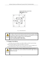
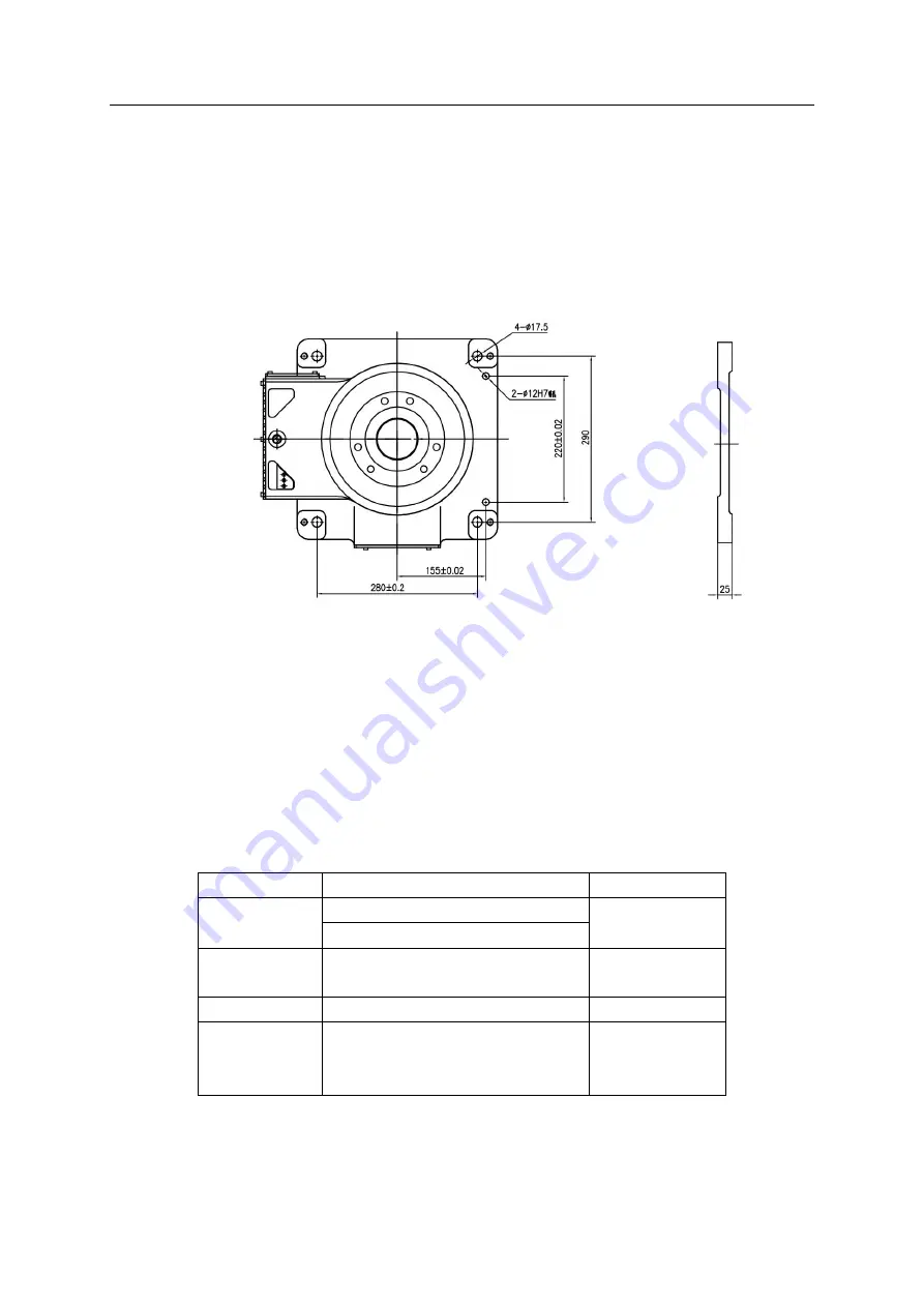
The dimensions of the interfaces of the base installation are shown in Figure 3-5 as follows:
Fig.3-5 Dimensions of Robot Base
3.2.3 Ground Mounting
Ground mounting requires the concrete foundation be firm; the strength level and load-bearing
capacity meet the relevant quality specifications; the thickness of the concrete be more than the filling
depth of the chemical bolts; the effectivity completely cover the fixed bottom plate to ensure the safety and
reliability of the bottom plate installation. Refer to GB50010-2010 Specification for Design of Concrete
Structures and GB/T50081-2002 Standard Testing Methods for Mechanical Properties of Ordinary
Concrete for concrete specifications and C20/C25 for strength level.
Table 3-1 Components Required for Robot Fixing
Name
Specifications
Quantity
Bottom plate
thickness
≥
30mm
1
reference area
(
600mm
×
600mm
)
Chemical Bolt
Group
M16 above
,
strength level
≥
4.8
8
Fixing screws
M16×55
,
strength level 12.9
4
Internal
threaded dowel
pin
M12x45
2
When installing on the ground, first fix the bottom plate on the ground. We recommend that the
thickness of the bottom plate should be more than 30mm. Use 8 chemical bolts of M16 or more to fix the
bottom plate on the ground. The base of the robot is firmly fixed on the bottom plate with M16 hexagon


