3-14
Section 3
— Installing The Editor
K5 Keyboard Connections
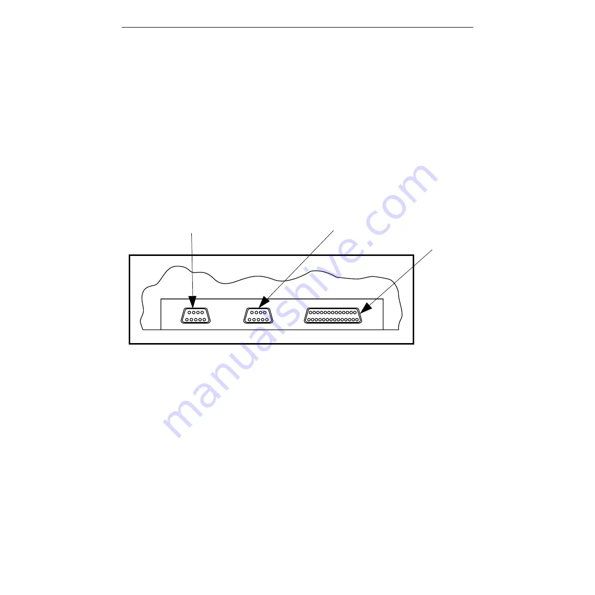
Figure 3-8 illustrates the rear panel of the K5 Keyboard and identifies the
connections which will be made to it. To make these connections, refer to
Figure 3-8 and proceed as follows:
1. Attach the keyboard cable from the RACK connector on the
Keyboard to the KEYBOARD connector on the Expansion Chassis.
2. Attach the power cable from the POWER connector on the Key-
board to an AC Power outlet.
3. Attach the cable from the Jogger panel to the JOG connector on the
Keyboard.
Figure 3-8. K5 Keyboard Connectors
4. If using the K5 Keyboard
a. Attach the K5 Keyboard cable to the KBD IN connector.
b. Attach the provided cable from the KBD OUT connector on the
Expansion Chassis to the KEYBOARD connector on the
Computing Chassis.
This completes physical installation of the K5 Keyboard. Proceed to the
Start-up Sequence.
0353-359
Rear View - K5 Keyboard
JOG (J5)
POWER (J2)
RACK (J1)


