background image


64


Use MIDI functionality

Advanced mode 1

Advanced mode 1

 of CONTROL CHANGE ASSIGN lets you specify the upper and lower 

limits of the control change value in addition to the items of Basic mode.

1.

Press the 

[EDIT]

 button.

2.

Slightly move the controller to which you want to assign a Control Change message. In 
the case of a button, press that button.
The display will indicate the number of the selected controller.

3.

Confirm what’s indicated, and press the 

[ENTER]

 button.

4.

Press the 

[CONTROL CHANGE]

 key and then press key 

[1]

.

The display will indicate “CC1.”

5.

Press the 

[ENTER]

 button.

6.

Input the channel.

7.

Press the 

[ENTER]

 button.

8.

Input the control change number.

9.

Press the 

[ENTER]

 button.

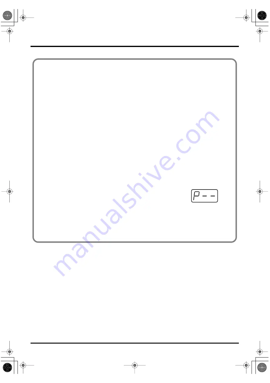
The following display will appear.

fig.p

10.

Specify the range of values. 
(

“Specifying the range of values (upper and lower limits)”

 (p. 62))

The display will indicate “P-.”

11.

Specify the output port. (

“Specifying the port”

 (p. 59))

12.

If you are making an assignment for a button, specify the button mode.
 (

“Specifying the button mode”

 (p. 59))

*1 Reference


*1 The -- area displays the currently set value. If it has not been set, the default setting will be displayed. Even if you change the type or mode 

of the MIDI message that is assigned, the default setting will be displayed. This will be lit if the value is the same as the currently set value, 

or will blink if the value is different.

PCR-M30/50/80.book 64 ページ 2005年11月10日 木曜日 午後2時49分

Содержание PCR-M30

Страница 1: ...64 GUATEMALA Casa Instrumental Calzada Roosevelt 34 01 zona 11 Ciudad de Guatemala Guatemala TEL 502 599 2888 HONDURAS Almacen Pajaro Azul S A de C V BO Paz Barahona 3 Ave 11 Calle S O San Pedro Sula Honduras TEL 504 553 2029 MARTINIQUE Musique Son Z I Les Mangle 97232 Le Lamantin Martinique F W I TEL 596 596 426860 Gigamusic SARL 10 Rte De La Folie 97200 Fort De France Martinique F W I TEL 596 59...

Страница 2: ... are Exposed to rain or are Dusty or are Subject to high levels of vibration 007 Make sure you always have the unit placed so it is level and sure to remain stable Never place it on stands that could wobble or on inclined surfaces 008c Be sure to use only the AC adaptor supplied with the unit Also make sure the line voltage at the installation matches the input voltage specified on the AC adaptor ...

Страница 3: ...ation or position does not interfere with their proper ventilation 102d Always grasp only the output plug or the body of the AC adaptor when plugging into or unplugging from this unit or an outlet 103b At regular intervals you should unplug the AC adaptor and clean it by using a dry cloth to wipe all dust and other accumulations away from its prongs Also disconnect the power plug from the power ou...

Страница 4: ...he unit to direct sunlight place it near devices that radiate heat leave it inside an enclosed vehicle or otherwise subject it to temperature extremes Excessive heat can deform or discolor the unit 355b When moved from one location to another where the temperature and or humidity is very different water droplets condensation may form inside the unit Damage or malfunction may result if you attempt ...

Страница 5: ...ht 559b When you need to transport the unit pack it in shock absorbent material Transporting the unit without doing so can cause it to become scratched or damaged and could lead to malfunction 561 Use only the specified expression pedal EV 5 sold separately By connecting any other expression pedals you risk causing malfunction and or damage to the unit Handling CD ROMs 801 Avoid touching or scratc...

Страница 6: ...ers 27 Windows 98 users 28 Getting Connected and Installing Drivers Macintosh 29 Mac OS X users 29 Installing the driver 29 Mac OS settings 30 Mac OS 9 users 32 Installing the driver 32 Setting the driver 33 Operation 39 Basic connections and MIDI flow 40 USB connections with your computer Sending MIDI messages to your application 40 MIDI flow 40 USB connections with your computer Using the PCR M3...

Страница 7: ...t ASSIGN COPY 82 Canceling a MIDI message assignment NO ASSIGN 83 Saving a Memory Set SAVE 84 Transmitting receiving bulk data BULK 85 Protecting a Memory Set PROTECT 88 System settings 89 F8 CLOCK ON OFF Keyboard 0 90 F8 CLOCK DEFAULT TEMPO Keyboard 1 90 F8 CLOCK PORT SET Keyboard 2 90 VELOCITY CURVE Keyboard 3 91 KEYBOARD PORT SET Keyboard 4 92 H ACTIVITY ON OFF Keyboard 5 92 USB MIDI DRIVER MOD...

Страница 8: ...of the PCR M30 50 80 For details on connections and driver installation refer to Setup Windows p 16 Macintosh p 29 Please use only the included USB cable If you require a replacement due to loss or damage please contact a EDIROL Roland Service Center listed in the Information section at the end of this manual CD ROM This contains drivers and editors for use with the PCR M30 50 80 Template sheets t...

Страница 9: ...at once p 55 Assign MIDI messages p 56 Note Assign p 57 Aftertouch Assign p 60 Control Change Assign p 63 Program Change Assign p 66 RPN NRPN Assign p 69 Sys Ex Assign p 72 Tempo Assign p 81 Copying a MIDI message assignment p 82 Canceling a MIDI message assignment p 83 Saving a memory set p 84 Transmitting receiving bulk data p 85 Protecting a memory set p 88 Making system settings F8 Clock p 90 ...

Страница 10: ...mages By using this with a V LINK compatible video device you can enjoy various video effects that are linked to your performance MEMORY Button Accesses memories that are stored within the PCR M30 50 80 MIDI CH Button Specifies the transmission channel current channel for the keyboard and bender PROGRAM CHANGE Button Transmits program change messages on the current channel EDIT Button Used to assi...

Страница 11: ...down the VELCRV button you can access a screen that lets you specify the velocity curve p 91 HEX Button When not in PLAY mode p 46 sets the input mode p 49 to hexadecimal HEX input mode DECIMAL Button When not in PLAY mode p 46 sets the input mode p 49 to decimal DECIMAL input mode Controllers B1 B6 You can assign MIDI messages to these controllers Assign MIDI messages p 56 8 9 10 11 12 13 PCR M30...

Страница 12: ...es p 56 Number Operating a controller will cause its current value to appear in the display for a time USB Lights if the PCR M30 50 80 is connected to your computer via USB DATA OUT This will blink when MIDI messages are transmitted via USB or MIDI OUT HEX Lights when the value shown in the display is hexadecimal fig panelB_60 15 14 14 15 PCR M30 50 80 book 12 ページ 2005年11月10日 木曜日 午後2時49分 ...

Страница 13: ...e ENTER button which you need to press to confirm the settings you ve made OCTAVE Press OCTAVE to shift the pitch of the keyboard up or down in steps of an octave When not in PLAY mode use these buttons to return to the previous setting item the BACK button or to cancel the setting and return to PLAY mode the CANCEL button BENDER Lever This lever can be used to modify the pitch or apply vibrato fi...

Страница 14: ... assign MIDI messages to these controllers as desired Assign MIDI messages p 56 Rear Panel DC Power on using the AC adaptor OFF Power is off USB Power on using a USB cable when not using the AC adaptor USB BUS power can be used when the PCR M30 50 80 is connected to your computer via a USB cable In this case the power will be supplied from your computer via the USB cable To use the PCR M30 50 80 w...

Страница 15: ...nected and Installing Drivers Macintosh p 29 What is a driver A driver is software that transfers data between the PCR M30 50 80 and application software running on your computer when your computer and the PCR M30 50 80 are connected by a USB cable The driver sends data from your application to the PCR M30 50 80 and from the PCR M30 50 80 to your application PCR M30 50 80 book 15 ページ 2005年11月10日 木...

Страница 16: ...rs The installation procedure will differ depending on your system Please proceed to one of the following sections depending on the system you use Windows XP users p 16 Windows 2000 users p 21 Windows Me 98 users p 25 You must log on using a user name with an administrative account type e g Administrator For details on user accounts please consult the system administrator of your computer Dependin...

Страница 17: ...FF connect the AC adaptor to the PCR M30 50 80 2 Connect the AC adaptor to an electrical outlet 3 Use the USB cable to connect the PCR M30 50 80 to your computer 11 Set the PCR M30 50 80 s power switch to the ON DC position Near the task bar your computer will indicate Found New Hardware Please wait If the screen indicates Windows can perform the same action each time you insert a disk or connect ...

Страница 18: ...iles from field and click OK drive name DRIVER USB_XP2K If the Found New Hardware Wizard asks you whether you want to connect to Windows Update choose No and then click Next If the What action do you want Windows to take Step 4 setting was not set to Ignore a Hardware Installation dialog box will appear A dialog box with a symbol will appear 1 Click Continue Anyway 2 Continue the installation A di...

Страница 19: ...ows restarts 1 Log on to Windows using the user name of an administrative account e g Administrator 2 Click the Windows start menu and from the menu that appears select Control Panel 3 In Pick a category click Performance and Maintenance 4 In or pick a Control Panel icon click the System icon The System Properties dialog box will appear 5 Click the Hardware tab and then click Driver Signing The Dr...

Страница 20: ...Control Panel icon click the System icon 2 Click the Advanced tab 3 At the right of the Performance field click Settings The Performance Options dialog box will appear 4 Click the Advanced tab fig 2 30a 5 In the Processor Scheduling field select Background services and click OK 6 In the System Properties dialog box click OK The System Properties dialog box will close Depending on how your system i...

Страница 21: ...he current setting Warn or Block Then change the setting to Ignore and click OK 5 Click OK to close the System Properties dialog box 6 Exit all currently running software Also close any open windows If you are using virus checking or similar software be sure to exit it as well 7 Prepare the CD ROM Insert the CD ROM into the CD ROM drive of your computer 8 Click the Windows Start menu From the menu...

Страница 22: ...ndows desktop double click the My Computer icon In the window that appears check the drive name of the CD ROM drive into which you inserted the CD ROM in step7 The drive name is the D or E displayed by the CD ROM drive Once the connections have been completed turn on power to your various devices in the order specified By turning on devices in the wrong order you risk causing malfunction and or da...

Страница 23: ...ed File signature verification If you changed the File signature verification p 21 setting restore the original setting after Windows restarts 1 After Windows restarts log in to Windows as a user with administrative privileges such as Administrator 2 In the Windows desktop right click the My Computer icon and from the menu that appears select Properties The System Properties dialog box will appear...

Страница 24: ...ttings 1 Click the Windows Start menu and from the menu that appears select Settings Control Panel In Control Panel double click the System icon 2 Click the Advanced tab 3 At the right of the Performance field click Performance Options The Performance Options dialog box will appear fig back2000 4 In the Application response field choose Background services and click OK 5 Click OK to close the Syst...

Страница 25: ...SB cable to connect the PCR M30 50 80 to your computer 1 With the power switch turned OFF connect the AC adaptor to the PCR M30 50 80 2 Connect the AC adaptor to an electrical outlet 3 Use the USB cable to connect the PCR M30 50 80 to your computer 7 Set the PCR M30 50 80 s power switch to the ON DC position 8 In the SetupInf dialog box click OK Windows Me 98 users To check the drive name In the W...

Страница 26: ... OUT connector select EDIROL PCR MIDI OUT 5 Close the Sounds and Audio Devices Properties dialog box Click OK to complete the settings Settings and checking Specifying the MIDI input output destination Windows XP users Depending on how your system is set up the Sounds and Audio Devices icon may be displayed directly in the Control Panel the Classic view In this case double click the Sounds and Aud...

Страница 27: ...se Media Player to play a sound module connected to the PCR s MIDI OUT connector select EDIROL PCR MIDI OUT 5 Close the Sounds and Multimedia Properties dialog box Click OK to complete the settings Windows 2000 Me users If the Sound and Multimedia icon is not displayed click Show all control panel options in the frame at the left Select the appropriate MIDI device for your system You do not necess...

Страница 28: ...at appears and click Apply If you want to use Media Player to play a sound module connected to the PCR s MIDI OUT connector select EDIROL PCR MIDI OUT 5 Close the Multimedia Properties dialog box Click OK to complete the settings Windows 98 users For details on the PCR s input output devices refer to Input output devices p 43 Select the appropriate MIDI device for your system You do not necessaril...

Страница 29: ...display will indicate Easy Install Click Install or Upgrade 7 The display will indicate Installing this software requires you to restart your computer when the installation is done Click Continue Installation 8 The display will indicate The software was successfully installed Click Restart to restart your computer This completes installation of the PCR driver Next make MIDI device settings Mac OS ...

Страница 30: ...s Four new external MIDI devices will appear 6 Specify a name for each new external device 1 Click Show Info 2 Enter the name in the Device Name field Enter the following for each new external device Mac OS settings First Second Third Fourth Device Name PCR MIDI IN OUT PCR PCR 1 PCR 2 Once the connections have been completed turn on power to your various devices in the order specified By turning o...

Страница 31: ...settings For details on MIDI device settings refer to the owner s manual for the software you are using When using the PCR with your software Before using the PCR with your software please note the following points Use the USB cable to connect the PCR to your computer before you start up your software Do not disconnect the USB cable from the PCR while your software is running Quit your software be...

Страница 32: ... Installing the driver OMS can be found in the OMS 2 3 8 E folder within the OMS Mac OS 9 8 folder of the CD ROM If you would like to know more about OMS refer to OMS_2 3_Mac pdf which can be found in the same folder If a PCR is already connected to your Macintosh when you install the driver a message like the following will appear when the Macintosh is started up Perform the steps described below...

Страница 33: ... fig 3 4 4 In the Opcode OMS Applications folder where you installed OMS double click OMS Setup to start it up fig 3 5_35 5 If a dialog box like the one shown here appears click Turn It Off A confirmation dialog box will then appear so click OK Setting the driver Once the connections have been completed turn on power to your various devices in the order specified By turning on devices in the wrong...

Страница 34: ...e one shown here will appear fig 3 9_35 8 From the Edit menu select OMS MIDI Setup In the OMS MIDI Setup dialog box that appears check Run MIDI in background and click OK fig 3 10_40 9 From the File menu choose Make Current If you are unable to select Make Current it has already been applied and you may continue to the next step 10 Verify that MIDI transmission and reception can be performed corre...

Страница 35: ...agram at the right If you hear sound the settings have been made correctly 12 Exit OMS Setup From the File menu choose Exit If the AppleTalk confirmation dialog box appears click OK to close the dialog box For details on the PCR s input output devices refer to Input output devices p 43 This completes installation of the driver Next make MIDI device settings in your sequencer or other software For ...

Страница 36: ...eMIDI and double click the FreeMIDI Setup icon to start it up 5 The first time you start up use the following procedure 1 A dialog box saying Welcome to FreeMIDI will appear Click Continue 2 The FreeMIDI Preferences dialog box will appear Click Cancel 3 The About Quick Setup dialog box will appear Click Cancel Once the connections have been completed turn on power to your various devices in the or...

Страница 37: ...the settings have been made correctly 10 Once again choose the MIDI menu command Check Connections to end the test 11 From the File menu choose Quit to exit FreeMIDI Setup If you are unable to select Open make settings as follows 1 From the File menu choose FreeMIDI Preference 2 Uncheck Use OMS when available 3 Close FreeMIDI Return to step 4 and continue the procedure For details on the PCR s inp...

Страница 38: ...38 Memo PCR M30 50 80 book 38 ページ 2005年11月10日 木曜日 午後2時49分 ...

Страница 39: ...will need to connect it to a sound module or computer The various controllers R1 R8 S1 S8 B1 B6 L1 L3 P1 P2 can be assigned almost any message you want to get the control you need for your particular setup For details on the messages that can be assigned refer to Assign MIDI messages p 56 PCR M30 50 80 book 39 ページ 2005年11月10日 木曜日 午後2時49分 ...

Страница 40: ...eyboard bender lever and other controllers those that have been set to PORT 1 will transmit data from here PORT 2 Of the keyboard bender lever and other controllers those that have been set to PORT 2 will transmit data from here BULK TRANSMISSION BULK data is transmitted from here USB cable AC adaptor It is not necessary to connect the AC adaptor if you are using a USB connection However with some...

Страница 41: ...IDI flow BULK RECEPTION BULK data is received here PORT 1 Of the keyboard bender lever and other controllers those that have been set to PORT 1 will transmit data from here PORT 2 Of the keyboard bender lever and other controllers those that have been set to PORT 2 will transmit data from here BULK TRANSMISSION BULK data is transmitted from here MIDI OUT MIDI sound module sold separately MIDI IN M...

Страница 42: ...data is received here PORT 1 Of the keyboard bender lever and other controllers those that have been set to PORT 1 will transmit data from here PORT 2 Of the keyboard bender lever and other controllers those that have been set to PORT 2 will transmit data from here BULK TRANSMISSION BULK data is transmitted from here MIDI sound module sold separately MIDI IN MIDI OUT AC adaptor R o l a n d DP seri...

Страница 43: ... will be input from the PCR M30 50 80 s MIDI IN connector Turn MIDI I F MODE ON as described in MIDI I F MODE p 94 PCR 1 PCR 2 These ports receive messages from the keyboard Bender Lever and controllers The port assignment determines how the keyboard Bender Lever and controllers are mapped to PCR 1 or PCR 2 You may find it convenient to select PCR 1 for messages used for real time performance on a...

Страница 44: ...ple even if you play your keyboard to send a note on message the software that receives this message will not produce a note instead it might interpret this message as meaning that the PLAY STOP button had been pressed The actual operation that will occur will depend on the software you are using fig midi port3 e Since the same MIDI message can be interpreted in completely different ways as descri...

Страница 45: ...nel Current channel p 48 for the keyboard bender lever Program Change mode PROGRAM CHANGE p 51 Press the PGOGRAM CHANGE Transmit program change messages on the Current channel p 48 Bank mode BANK p 52 Simultaneously press the PGOGRAM CHANGE and the MIDI CH Transmit bank select mes sages MSB LSB on the Current channel p 48 Panic mode PANIC p 53 Simultaneously press the PGOGRAM CHANGE and the EDIT S...

Страница 46: ...er to send MIDI messages from the PCR M30 50 80 to your application perform the following steps 1 Set the MIDI channel the PCR M30 50 80 will use to transmit to the same channel on the application is using to receive on Use MIDI Channel mode to set the MIDI transmit channel MIDI Channel mode p 48 2 Select a sound on your MIDI sound module Selecting Sounds on a Sound Module p 50 3 Once you have fin...

Страница 47: ...pends on the set tings of your sound module Modifying the Sound of Notes Modulation Push the Bender Lever away from you to transmit Modulation messages changing the sound in real time usually by adding a vi brato effect The type of change this produces in the sound depends on the set tings of your sound module Changing Octaves Octave Shift You can press OCTAVE or OCTAVE to raise or lower the pitch...

Страница 48: ...o specify the desired channel number 3 Press the ENTER button The setting will be cancelled if you press another button instead of the ENTER button The current channel has now been set Setting the MIDI Transmit Channel MIDI Channel mode MIDI CH DEC Change the current value by 1 INC Change the current value by 1 00 0F The input value HEX 00 0F DECIMAL 1 16 Current channel The current channel is the...

Страница 49: ...ified for each con troller Setting the input mode fig hexdec If you are not in Play mode you can use one of two ways to input a numerical value into the PCR M30 50 80 Decimal input mode or Hexadecimal input mode If you want to input decimal numbers press the DECIMAL button If you want to input hexadecimal numbers press the HEX button When you turn on the power the PCR M30 50 80 will start up in De...

Страница 50: ...ecting Sounds on a Sound Module Sending Program Change Bank Select Massages What is a bank MIDI sound modules organize their numerous sounds in various groups according to the category of sound These groups are called banks Program Change messages can only select sounds within the same bank but by using these in conjunction with Bank Select messages you can select different variations of sound The...

Страница 51: ... also light according to the input mode p 49 2 Use the DEC INC buttons or the 0 F keys of the keyboard to specify the program change you want to transmit 3 Press the ENTER button The setting will be cancelled if you press another button instead of the ENTER button The program change has now been transmitted Program Change mode PROGRAM CHANGE DEC Change the current value by 1 INC Change the current...

Страница 52: ... Press the ENTER button The setting will be cancelled if you press another button instead of the ENTER button fig BANK 3 4 Next specify the bank select LSB CC 32 The display will indicate the most recently transmitted bank select LSB value Use the DEC INC buttons or the 0 F keys of the keyboard to specify the bank select LSB that you want to transmit 5 Press the ENTER button The setting will be ca...

Страница 53: ...l controllers messages will be transmitted on all channels fig panic 1_80 fig panic 1 Simultaneously press the PROGRAM CHANGE button and EDIT button The PROGRAM CHANGE button and EDIT button will light 2 Press the ENTER button The PROGRAM CHANGE button and EDIT button will blink The Panic function has now been executed Transmitting a Reset message What to do if there are stuck MIDI notes Panic Mod...

Страница 54: ... or the 0 F keys of the keyboard to specify the memory number that you want to recall 3 Press the ENTER button The setting will be cancelled if you press another button instead of the ENTER button The memory has now been recalled Changing the Memory Sets Memory mode MEMORY 1 2 3 For details on customizing editing the controller settings refer to Assign MIDI messages p 56 If you edit the controller...

Страница 55: ... you want to record the state of these controllers together at the beginning of a song in your sequencer as the initial values fig snap 1_80 fig snap 1 Simultaneously press the MEMORY button and the MIDI CH button The MEMORY and MIDI CH buttons will light 2 Press the ENTER button The MEMORY and MIDI CH button will blink several times The snapshot will be transmitted Transmitting the current contro...

Страница 56: ...CHANGE CONTROL CHANGE ASSIGN p 63 PROGRAM CHANGE PROGRAM CHANGE ASSIGN p 66 RPN RPN NRPN ASSIGN p 69 NRPN RPN NRPN ASSIGN p 69 Sys Ex Sys Ex ASSIGN p 72 TEMPO 20 250 TEMPO ASSIGN p 81 Edit mode EDIT How Basic mode and Advanced mode differ The assignments NOTE AFTERTOUCH CONTROL CHANGE PROGRAM CHANGE RPN NRPN Sys Ex can be made either in Basic mode or Advanced mode Use the mode that is appropriate ...

Страница 57: ...controller number and press the ENTER button fig nt0 4 Press the NOTE key The display will indicate NT0 fig c 5 Press the ENTER button The display will indicate C 6 Input the channel Use the DEC INC buttons or the 0 F keys to specify the channel fig n 7 Press the ENTER button The display will indicate N 8 Input the note number Use the DEC INC buttons or the 0 F keys to specify the note number 9 Pr...

Страница 58: ... the number of the selected controller 3 Verify that the display indicates the correct controller and press the ENTER button 4 Press the NOTE key and then press key 1 The display will indicate NT1 5 Press the ENTER button 6 Input the channel 7 Press the ENTER button 8 Input the note number fig v 9 Press the ENTER button The display will indicate V 10 Input the velocity fig p 11 Press the ENTER but...

Страница 59: ...itted and will go dark when an Off message is transmitted Specifying the port When you are making Assign settings in Edit mode p 56 and have selected Advanced mode you must specify the USB port to which the message assigned to the controller will be sent when using a USB connection 1 Press a key 1 3 to select the port 2 Press the ENTER button For details on the port refer to Input output devices p...

Страница 60: ...e 0 F keys to specify the channel 7 Press the ENTER button 8 If you are making an assignment for a button specify the button mode Specifying the button mode p 59 Mode Keyboard Message Value range Port Basic mode 0 Channel Pressure 0 127 00 7FH Port 1 Advanced mode 1 1 Channel Pressure Upper and lower limits are assignable Assignable Advanced mode 2 2 Polyphonic Key Pressure 0 127 00 7FH Port 1 Adv...

Страница 61: ...icates the correct controller and press the ENTER button fig at1 4 Press the AFTERTOUCH key and then press a key 1 3 The display will indicate the selected mode 5 Press the ENTER button 6 Input the channel 7 Press the ENTER button 8 If you are using Advanced modes 2 or 3 input the note number 9 If you are using Advanced modes 2 or 3 Press the ENTER button 10 If you are using Advanced modes 1 or 3 ...

Страница 62: ...you are now inputting Then switch back to Decimal input mode and continue Setting the input mode p 49 fig max 1 The following display will appear 2 Use the DEC INC buttons or the 0 F keys to specify the upper limit fig min 3 Press the ENTER button The following display will appear 4 Use the DEC INC buttons or the 0 F keys to specify the lower limit 5 Press the ENTER button 1 Reference 1 Reference ...

Страница 63: ...the channel fig n 7 Press the ENTER button The display will indicate N 8 Use the DEC INC buttons or the 0 F keys to specify the control change number 9 Press the ENTER button 10 If you are making an assignment for a button specify the button mode Specifying the button mode p 59 Mode keyboard Value range Port Basic mode 0 0 127 00 7FH PORT 1 Advanced mode 1 1 Upper and lower limits are assignable A...

Страница 64: ...el 7 Press the ENTER button 8 Input the control change number 9 Press the ENTER button The following display will appear fig p 10 Specify the range of values Specifying the range of values upper and lower limits p 62 The display will indicate P 11 Specify the output port Specifying the port p 59 12 If you are making an assignment for a button specify the button mode Specifying the button mode p 59...

Страница 65: ...ange message The display will indicate the number of the selected controller 3 Confirm what s indicated and press the ENTER button 4 Press the CONTROL CHANGE key and then press key 2 The display will indicate CC2 5 Press the ENTER button 6 Input the channel 7 Press the ENTER button 8 Input the control change number Use the DEC INC buttons or the 0 F keys to specify the control change number fig p ...

Страница 66: ...te N 8 Use the DEC INC buttons or the 0 F keys to specify the program change number 9 Press the ENTER button If you assign Basic mode to S1 S8 R1 R8 or P2 moving the controller to the maximum position will transmit the assigned control change messages Mode Number Effect Bank Port Basic mode 0 Fixed value Not output PORT 1 Advanced mode 1 1 Upper and lower limits are assignable Not output PORT 1 Ad...

Страница 67: ...ced mode 2 Transmitting bank data 4 Press the PROGRAM CHANGE key and then press key 2 5 Press the ENTER button 6 Input the channel 7 Press the ENTER button fig BANK 2 8 Specify the bank select MSB CC 00 Use the DEC INC buttons or the 0 F keys to specify the MSB 9 Press the ENTER button fig BANK 3 10 Specify the bank select LSB CC 32 Use the DEC INC buttons or the 0 F keys to specify the LSB 11 Pre...

Страница 68: ...tted by Advanced Mode 3 or 4 or in Program Change mode p 51 Program changes transmitted by basic mode or advanced modes 1 and 2 will not affect the increment decrement functions Advanced modes 3 and 4 Advanced mode 3 lets you assign the Program Change Decrement function PC DEC to a controller Advanced mode 4 lets you assign the Program Change Increment function PC INC to a controller 1 Press the E...

Страница 69: ...he display will blink C 6 Input the channel Use the DEC INC buttons or the 0 F keys to specify the channel 7 Press the ENTER button fig BANK 2 8 Use the DEC INC buttons or the 0 F keys to specify the RPN MSB CC 101 or NRPN MSB CC 99 9 Press the ENTER button Mode Keyboard Data entry MSB CC 6 range Data entry LSB CC 38 range Port Basic mode 0 0 127 00 7FH Not transmitted PORT 1 Advanced mode 1 1 Upp...

Страница 70: ...tons or the 0 F keys to specify the RPN LSB CC 100 or NRPN LSB CC 98 11 Press the ENTER button 12 If you are making an assignment for a button specify the button mode Specifying the button mode p 59 1 Reference PCR M30 50 80 book 70 ページ 2005年11月10日 木曜日 午後2時49分 ...

Страница 71: ...nnel 7 Press the ENTER button 8 Use the DEC INC buttons or the 0 F keys to specify the RPN MSB CC 101 or NRPN MSB CC 99 9 Press the ENTER button 10 Use the DEC INC buttons or the 0 F keys to specify the RPN LSB CC 100 or NRPN LSB CC 98 11 Press the ENTER button fig p 12 Specify the lower limit of the data entry MSB CC 06 value Specifying the range of values upper and lower limits p 62 The display ...

Страница 72: ...at s indicated and press the ENTER button fig se0 4 Press the SYSTEM Ex key 5 If you want to select an Advanced mode press a key from 1 to 4 The selected mode will blink in the display 6 Confirm what s indicated and press the ENTER button Then continue with the procedure described in Basic mode or Advanced mode For some actual examples of settings refer to Examples of assigning system exclusive me...

Страница 73: ...of bytes you want to input 8 Press the ENTER button 9 Use the 0 F keys to input the first byte 10 Press the ENTER button 11 Input the second and subsequent bytes in the same way 12 After you have input the number of bytes you specified in step 7 the PCR M30 50 80 will check whether the messages you ve input are indeed valid MIDI messages If there is a problem the display will indicate ERR In this ...

Страница 74: ...m Start will be cancelled 2 Press the ENTER button 3 Continue inputting data fig cs1 4 Press the CHECKSUM key at the location where the checksum should be inserted The display will indicate CS1 Checksum type 1 5 Press the ENTER button Checksum types There are two types of checksum as follows Switching the type fig cs12 If you want to switch to type 2 press the 2 key after you press CHECKSUM in ste...

Страница 75: ...the ENTER button 4 If you selected DT1 through DT4 the display will indicate DT Press the ENTER button Data number Data type Default range Target of range setting Example specified upper lower limits DT0 7bit 00H 7F Specify the range of data 00H 7FH 04 45 lower limit 4H upper limit 45H DT1 4bit 4bit 0H 0H FH FH Specify the range of the first byte 0H FH sec ond byte is fixed at 0H FH 0 0 D F lower ...

Страница 76: ...ion where you want to input the channel block number to select 0CH for the channel or 0BL for the block fig chbl 2 Use the 0 7 keys to input the value of the upper four bits The 0 in the display will change to the numerical value that you input 3 Press the ENTER button Current channel 1 2 3 4 5 6 7 8 9 10 11 12 13 14 15 16 CH 0 1 2 3 4 5 6 7 8 9 A B C D E F BL 1 2 3 4 5 6 7 8 9 0 A B C D E F DATA ...

Страница 77: ...NTER button The display will indicate F0 which is the first byte beginning status of a system exclusive message This cannot be changed This cannot be changed 6 Confirm what s indicated and press the ENTER button 7 Use the 7 and E keys to input the second byte 7E 8 Confirm what s indicated and press the ENTER button 9 Use the 7 and F keys to input the third byte 7F 10 Confirm what s indicated and p...

Страница 78: ... system exclusive message This cannot be changed 6 Confirm what s indicated and press the ENTER button 7 Use the 7 and F keys to input the second byte 7F 8 Confirm what s indicated and press the ENTER button 9 Input the third fourth and fifth bytes in the same way 10 Since the sixth byte is the data area press the DATA key and then press 3 The display will indicate DT3 11 Confirm what s indicated ...

Страница 79: ... exclusive message This cannot be changed 6 Confirm what s indicated and press ENTER 7 Use the 4 and 1 keys to input the second byte 41 8 Confirm what s indicated and press ENTER 9 Input the third fourth and fifth bytes in the same way 10 Since the sixth byte is the beginning of the checksum calculation area press the CHECKSUM key to specify this byte as the beginning of the area for which the che...

Страница 80: ...rm what s indicated and press ENTER 21 Press the F and then 7 keys to input the ending status F7 22 Confirm what s indicated and press ENTER 23 Next specify an upper limit value of 58 for the data area 24 Press ENTER 25 Specify a lower limit value of 40 for the data area 26 Press ENTER 27 Specify the output port Specifying the port p 59 28 If you are making an assignment for a button specify the b...

Страница 81: ...assign TEMPO In the case of a button press that button The display will indicate the number of the selected controller 3 Confirm what s indicated and press the ENTER button 4 Press the TEMPO key The display will indicate TMP fig tmp 5 Confirm what s indicated and press the ENTER button 6 If you are making the assignment for a button specify the button mode Specifying the button mode p 59 In the ca...

Страница 82: ...e display will indicate the number of the selected controller 3 Confirm what s indicated and press the ENTER button 4 Slightly move the controller whose assignment you want to copy the copy source In the case of a button press that button fig cpy The display will indicate CPY fig s 1 5 Press the ENTER button The display will blink the copy source controller number 6 Confirm what s indicated and pr...

Страница 83: ...ly move the controller whose assignment you want to cancel In the case of a button press that button The display will indicate the number of the selected controller 3 Confirm what s indicated and press the ENTER button fig noa 4 Press the NO ASSIGN key The display will indicate NOA 5 Press the ENTER button fig yes 6 The display will blink YES so press the ENTER button once again Canceling a MIDI m...

Страница 84: ...C INC buttons or the 1 F keys to specify the save destination memory number The specified memory number will blink in the display 5 Confirm what s indicated and press the ENTER button Saving a Memory Set SAVE About the memories of the PCR The PCR has the following sixteen memories Current memory is a location into which you can recall one of these memories In order to use one of the saved memories...

Страница 85: ... will blink BLR Bulk Receive fig rs 3 Confirm what s indicated and press the ENTER button The display will indicate RS and the S will blink 4 Use the DEC INC buttons or the 0 1 keys to select the mode fig rs1 5 Confirm what s indicated and press the ENTER button The third digit of the display will blink and the PCR M30 50 80 will wait to receive bulk data Transmitting receiving bulk data BULK 0 SI...

Страница 86: ...icated and press the ENTER button About the display in Bulk mode fig bulk dis Transmit Receive ALL BULK SINGLE BULK 1st digit indicates Receive mode or Transmit mode receiving transmitting Waiting to receive blinking Waiting to transmit blinking Transmitting 2nd digit Single Bulk or All Bulk 3rd digit indicates Transmitting Receiving Waiting states Error display fig err If the data could not be re...

Страница 87: ...d the PCR M30 50 80 will wait to transmit bulk data 8 Press the ENTER button On your sequencer software specify PCR 2 as the MIDI input device For details on this setting refer to the manual of your sequencer software For details on the port that will be used to transfer bulk data refer to Input output devices p 43 fig end 9 When the PCR finishes receiving the bulk data the display will indicate E...

Страница 88: ...EDT fig ptc 2 Press the PROTECT key The display will blink PTC 3 Confirm what s indicated and press the ENTER button 4 The display will show the current setting 5 Use the DEC INC buttons or the 0 1 keys to select the mode 6 Press the ENTER button Protecting a Memory Set PROTECT 0 PROTECT OFF Allow changes 1 PROTECT ON Prohibit changes PCR M30 50 80 book 88 ページ 2005年11月10日 木曜日 午後2時49分 ...

Страница 89: ...ur playing strength By setting the VELOCITY CURVE you can modify the keyboard s sensitivity and the curve that is followed when the velocity value changes 1 MEDIUM p 91 KEYBOARD PORT SET 4 Specify the port from which messages produced by the BENDER lever of the keyboard are to be trans mitted PORT 1 p 92 H ACTIVITY ON OFF 5 Turn this ON if you are using certain applications such as Pro Tools LE Wh...

Страница 90: ...y F8 CLOCK DEFAULT TEMPO Value range 20 250 The specified value will indicate in the display 5 Press the ENTER button Perform steps 1 3 4 Use the DEC INC buttons or the 1 3 keys to specify F8 CLOCK PORT SET Specifying the port p 59 The specified port will indicate in the display 5 Press the ENTER button F8 CLOCK ON OFF Keyboard 0 F8 CLOCK DEFAULT TEMPO Keyboard 1 F8 CLOCK PORT SET Keyboard 2 0 OFF...

Страница 91: ...tly played notes High velocity values will be produced even if you play the keyboard softly 4 2 MEDIUM The keyboard sensitivity will be normal 5 2 HEAVY High velocity values will be produced only if you play the keyboard strongly 6 3 LIGHT Variations in your playing strength will produce natu ral sounding changes in volume High velocity values will be produced even if you play the keyboard softly ...

Страница 92: ...ify the USB MIDI DRIVER MODE FPT Fast Processing Technology for MIDI Transmission Effective use is made of the USB bandwidth according to the amount of MIDI data to be transmitted ensuring that MIDI data processing will always occur optimally 5 Press the ENTER button KEYBOARD PORT SET Keyboard 4 H ACTIVITY ON OFF Keyboard 5 USB MIDI DRIVER MODE Keyboard 6 0 Original driver FPT technology is used t...

Страница 93: ...on The display will blink YES 6 Press the ENTER button STARTUP MEMORY Keyboard 7 0 GM2 MEMORY When the PCR starts up memory number 0 GM2 will be loaded into current memory p 84 regardless of the state in which the power was turned off 1 LAST ACCESS MEMORY Upon power up the PCR M30 50 80 will recall the mem ory that was last recalled or saved into current memory p 84 FACTORY RESET Keyboard 8 PCR M3...

Страница 94: ...e sent to the computer 1 MIDI I F MODE OFF MIDI messages received by the PCR M30 50 80 are not output from the PCR M30 50 80 MIDI messages will be transferred be tween the PCR M30 50 80 and the computer or between the PCR 04 9 3 and an external MIDI device PCR M1 PC USB EDIROL PCR EDIROL PCR MIDI OUT EDIROL PCR 2 EDIROL PCR 1 EDIROL PCR MIDI IN MIDI OUT MIDI IN MIDI I F MODE ON PORT 1 PORT 2 MIDI ...

Страница 95: ... transmitted at this fixed value regardless of how strongly you play the keys You can use the Key Velocity mode to specify a fixed value if you don t want your playing dynamics to have an effect 4 Use the DEC INC buttons or the keyboard to specify the Key Velocity mode 5 Press the ENTER button KEY VELOCITY Keyboard A 0 TOUCH Velocity values will be transmitted according to the key board sensitivit...

Страница 96: ...When you press the V LINK button once again the PCR will transmit a V LINK OFF message and will exit V LINK mode V LINK OFF Clip Ctrl Rx MIDI ch 16 Color Ctrl Rx MIDI ch 16 Sender Model Name EDIROL PCR Set the MIDI channel to 16 for parameters that you want to control via V LINK PCR M30 50 80 book 96 ページ 2005年11月10日 木曜日 午後2時49分 ...

Страница 97: ...eshooting information and explanations of convenient functions You may read this material as necessary Memory sets p 98 Troubleshooting p 104 MIDI implementation p 112 Main specifications p 117 PCR M30 50 80 book 97 ページ 2005年11月10日 木曜日 午後2時49分 ...

Страница 98: ... from the following website GM2 SET MEMORY 0 fig gm2 tmp Parameter Message Hex Range Hex Ch Por t R1 FILTER CUTOFF CC 74 4A 0 00 127 7F 1 1 R2 FILTER RESONANCE CC 71 47 0 00 127 7F 1 1 R3 VIBRATO RATE CC 76 4C 0 00 127 7F 1 1 R4 VIBRATO DEPTH CC 77 4D 0 00 127 7F 1 1 R5 VIBRATO DELAY CC 78 4E 0 00 127 7F 1 1 R6 COARSE TUNING RPN 0 2 00 02 0 00 127 7F 1 1 R7 FINE TUNING RPN 0 1 00 01 0 0 00 00 127 ...

Страница 99: ...7F 11 2 P1 HOLD CC 64 40 0 00 127 7F 1 1 P2 EXPRESSION CC 11 0B 0 00 127 7F 1 1 Parameter Message Hex Range Hex Ch Port R1 TRACK 1 1 CC 16 10 0 00 127 7F 1 2 R2 TRACK 2 1 CC 16 10 0 00 127 7F 2 2 R3 TRACK 3 1 CC 16 10 0 00 127 7F 3 2 R4 TRACK 4 1 CC 16 10 0 00 127 7F 4 2 R5 TRACK 5 1 CC 16 10 0 00 127 7F 5 2 R6 TRACK 6 1 CC 16 10 0 00 127 7F 6 2 R7 TRACK 7 1 CC 16 10 0 00 127 7F 7 2 R8 TRACK 8 1 C...

Страница 100: ...K 14 SOLO CC 37 25 0 00 127 7F 16 2 L1 CC 20 14 0 00 127 7F 16 2 L2 Stop CC 21 15 0 00 127 7F 16 2 L3 Rec CC 23 17 0 00 127 7F 16 2 P1 HOLD CC 64 40 0 00 127 7F 1 1 P2 EXPRESSION CC 11 0B 0 00 127 7F 1 1 Parameter Message Hex Range Hex Ch Port R1 TRACK 1 PAN CC 72 48 0 00 127 7F 16 2 R2 TRACK 2 PAN CC 73 49 0 00 127 7F 16 2 R3 TRACK 3 PAN CC 74 4A 0 00 127 7F 16 2 R4 TRACK 4 PAN CC 75 4B 0 00 127 ...

Страница 101: ...P B0 0F 0E B0 2F dd ON 43 OFF 03 2 L3 PLAY B0 0F 0E B0 2F dd ON 44 OFF 04 2 P1 HOLD CC 64 40 0 00 127 7F 1 1 P2 EXPRESSION CC 11 0B 0 00 127 7F 1 1 Parameter Message Hex Range Hex Ch Port R1 REVERB MACRO F0 41 10 42 12 40 01 30 dd SUM F7 0 00 7 07 1 R2 REVERB CHARACTER F0 41 10 42 12 40 01 31 dd SUM F7 0 00 7 07 1 R3 REVERB PRE LPF F0 41 10 42 12 40 01 32 dd SUM F7 0 00 7 07 1 R4 REVERB TIME F0 41...

Страница 102: ...NUE FB 2 P1 HOLD CC 64 40 0 00 127 7F 1 1 P2 EXPRESSION CC 11 0B 0 00 127 7F 1 1 Parameter Message Hex Range Hex Ch Port R1 DELAY MACRO F0 41 10 42 12 40 01 50 dd SUM F7 0 00 9 09 1 R2 DELAY PRE LPF F0 41 10 42 12 40 01 51 dd SUM F7 0 00 7 07 1 R3 DELAY TIME RATIO LEFT F0 41 10 42 12 40 01 53 dd SUM F7 1 01 120 78 1 R4 DELAY TIME CENTER F0 41 10 42 12 40 01 52 dd SUM F7 1 01 115 73 1 R5 DELAY TIME...

Страница 103: ...3 10 4C 08 0ch 05 dd F7 MONO 00 POLY 01 CURRENT CH 1 B6 XG SYSTEM ON F0 43 10 4C 00 00 7E 00 F7 1 L1 STOP FC 2 L2 START FA 2 L3 CONTINUE FB 2 P1 HOLD CC 64 40 0 00 127 7F 1 1 P2 EXPRESSION CC 11 0B 0 00 127 7F 1 1 Parameter Message Hex Range Hex Ch Port R1 MW PITCH CONTROL F0 43 10 4C 08 0ch 1D dd F7 0 00 64 40 127 7F CURRENT CH 1 R2 MW FILTER CONTROL F0 43 10 4C 08 0ch 1E dd F7 0 00 64 40 127 7F ...

Страница 104: ...CD ROM drive Installation is not possible unless the CD ROM included with the PCR M30 50 80 is inserted in your CD ROM drive Make sure that the CD ROM is correctly inserted into your CD ROM drive Are you installing the software from a networked CD ROM drive The software cannot be installed from a networked CD ROM drive Be sure to close all other programs before installation Is the CD ROM or the le...

Страница 105: ...16 You attempted to install using the procedure in Installing the driver but the installation was not successful Use the procedure in Deleting the driver p 109 to uninstall the driver Then set the PCR to the following driver mode turn the PCR s power on again and install the driver once again USB MIDI DRIVER MODE p 92 0 Original driver Is OMS or FreeMIDI installed Mac OS 9 The PCR M30 50 80 driver...

Страница 106: ...B Check the settings of your computer In some cases the PCR M30 50 80 cannot be used with a bus powered hub a hub that does not contain a power supply Please use a self powered hub a hub that contains a power supply Is USB enabled on your computer Refer to the operation manual for your computer and make sure that USB is enabled Does your computer meet the USB specifications If you are using a comp...

Страница 107: ...l Signature Not Found dialog box Did you make Driver Signing Options In order to install re install the driver you must make the settings described in Driver Signing Options Windows XP p 16 Windows 2000 p 21 Found unknown device appears even though you installed the driver If your computer or USB hub has two or more USB connectors and you connect the PCR M30 50 80 to a USB connector to which the P...

Страница 108: ... did not correctly detect and initialize the PCR M30 50 80 Leave the PCR M30 50 80 s USB cable connected and restart your Macintosh If it is still not detected shut down your Macintosh and then restart it In some cases the PCR M30 50 80 will not be detected if you have connected it to the USB connector located on the keyboard of the Macintosh Please connect it to a USB connector on the Macintosh i...

Страница 109: ...ows Start menu choose Run In the Run dialog box input the following into the Open field and click OK Windows XP 2000 users D DRIVER USB_XP2K Uninstal EXE Windows Me 98 users D DRIVER USB_ME98 Uninstal EXE The drive name D may be different on your system Use the drive name for your CD ROM drive 4 Follow the on screen instructions to uninstall the driver Macintosh Mac OS 9 users 1 Turn off the power...

Страница 110: ... manual of the software you are using Was the driver installed correctly In order for you to play back audio data via the PCR M30 50 80 the driver must be installed For installation and settings refer to Getting Connected and Installing Drivers Windows p 16 Macintosh p 29 Are you running multiple applications If multiple applications are running simultaneously an error message may appear If this o...

Страница 111: ...mputer with the PCR M30 50 80 disconnected and then connect the PCR M30 50 80 On a computer that uses a USB keyboard starting up the computer with the PCR M30 50 80 already connected may cause operation to become unstable In this case start up the computer with the PCR M30 50 80 disconnected and then connect the PCR M30 50 80 PCR M30 50 80 book 111 ページ 2005年11月10日 木曜日 午後2時49分 ...

Страница 112: ...ch exclusive message that is sent Also you must leave an interval of at least 500 ms after transmitting one set of bulk dump data 2 Transmit data Channel voice messages In addition to the channel voice messages that can be transmitted in each mode the PCR M30 50 80 lets you assign any channel voice message to any controller and transmit it Note off Status 2nd byte 3rd byte 9nH kkH 00H n MIDI chann...

Страница 113: ...trollers Controller number 121 Status 2nd byte 3rd byte BnH 79H 00H n MIDI channel number 0H FH Ch 1 16 Transmitted in Panic mode All notes off Controller number 123 Status 2nd byte 3rd byte BnH 7BH 00H n MIDI channel number 0H FH Ch 1 16 Transmitted in Panic mode System common message On the PCR M30 50 80 you can assign the following system common messages to any controller and transmit them MTC ...

Страница 114: ...00H 00H 70H Byte Explanation F0H Exclusive status 41H ID number Roland 10H Device ID For the PCR M30 50 80 fixed at 10H 00H 51H Model ID V LINK 12H Command ID DT1 10H 00H 00H Address 00H V LINK OFF 51H Checksum F7H EOX End of Exclusive Sender Model Name Transmitted when entering V LINK mode Status Data byte Status F0H 41H 10H 00H 51H 12H F7H 10H 71H 00H 45H 44H 49H 52H 4FH 4CH 20H 50H 43H 52H 00H ...

Страница 115: ... What is the decimal expression of the 7 bit hexadecimal value 12 34H From the preceding table 12H 18 and 34H 52 Thus this is 18 x 128 52 2356 Example3 What is the decimal expression of the nibble expressed value 0A 03 09 0D From the preceding table 0AH 10 03H 3 09H 9 and 0DH 13 Thus this is 10 x 16 3 x 16 9 x 16 13 41885 Example4 What is the nibble expressed value of decimal 1258 1258 16 78 quoti...

Страница 116: ...est Clock Commands All Sound Off Reset All Controllers Local On Off All Notes Off Active Sensing System Reset 1 1 16 Mode 3 OMNI ON OFF MONO POLY O 9n v 1 127 O 9n v 0 O 0 127 O O O O 0 127 O O O 0 127 O O O O 1 120 O 1 121 O O 1 123 O O X X X X X X X X X X X X X X X O X X X X X X X X X X X 1 When PANIC is transmitted MIDI KEYBOARD CONTROLLER Model PCR M30 50 80 Date Nov 01 2004 Version 1 00 MIDI ...

Страница 117: ... DC IN Jack Power Supply DC 9 V AC Adaptor or USB Bus Powered Current Draw 300 mA AC Adaptor 300 mA USB Bus Power Dimensions PCR M30 600 W x 232 D x 86 4 H mm 23 5 8 W x 9 3 16 D x 3 7 16 H inches PCR M50 833 W x 232 D x 86 4 H mm 32 13 16 W x 9 3 16 D x 3 7 16 H inches PCR M80 1 000 W x 232 D x 86 4 H mm 39 3 8 W x 9 3 16 D x 3 7 16 H inches Weight PCR M30 2 4 kg 5 lbs 5 oz excluding AC adaptor P...

Страница 118: ...sure 60 98 113 Channel Voice Messages 112 Checksum 72 74 79 115 Checksum types 74 Specifying the checksum 74 Continue 113 Control Change 112 Assigning a control change message 63 64 Control Change Assign 56 63 64 Control Change message 56 63 Simulating the operation of a conventional rotary encoder 65 Specifying the upper and lower limits of the control change value 64 Controllers 10 12 Copy 82 Cu...

Страница 119: ...g Pitch Changes to Notes 47 Changing Octaves 47 Modifying the Sound of Notes 47 Transpose the Pitch of the Keyboard 47 G Generic driver 92 GM2 Set 84 98 GM2 System On 77 GS 101 GS Set 101 102 H H Activity On Off 89 92 H Compatible Set 101 HEX Button 11 Hexadecimal HEX input mode 11 49 I Identity Reply 114 Identity Request Message 112 INC Button 11 Input Mode Decimal 49 Hexadecimal 49 Setting the I...

Страница 120: ...rties 27 28 N No Assign 83 Note Note Assign 56 57 Note Message 56 57 Specifying the velocity value 58 Note Off 112 Note On 112 NRPN RPN NRPN Assign 56 69 RPN NRPN Message 56 69 O Octave 13 47 Octave 13 Octave Shift 47 Octave Shift 47 OMNI 49 OMNI Off 49 OMNI On 49 OMS 33 Original Driver 92 Other Device 105 P Panic 45 53 Panic Mode 45 53 PC DEC 66 PC INC 66 PCR 43 PCR 1 43 PCR 2 43 PCR MIDI IN 43 P...

Страница 121: ...2 114 System Exclusive message 56 72 112 114 System 89 System Common Message 113 System Message 72 System Realtime Message 113 System Reset 113 System Settings F8 Clock Dfault Tempo 89 F8 Clock On Off 89 F8 Clock Port Set 89 Factory Reset 89 H Activity On Off 89 Key Velocity 89 Keyboard Port Set 89 MIDI I F Mode 89 Startup Memory 89 USB MIDI Driver Mode 89 Velocity Curve 89 T Tempo F8 Clock messag...

Страница 122: ...122 Memo PCR M30 50 80 book 122 ページ 2005年11月10日 木曜日 午後2時49分 ...

Страница 123: ... are Exposed to rain or are Dusty or are Subject to high levels of vibration 007 Make sure you always have the unit placed so it is level and sure to remain stable Never place it on stands that could wobble or on inclined surfaces 008c Be sure to use only the AC adaptor supplied with the unit Also make sure the line voltage at the installation matches the input voltage specified on the AC adaptor ...

Страница 124: ... 593 4 2302364 GUATEMALA Casa Instrumental Calzada Roosevelt 34 01 zona 11 Ciudad de Guatemala Guatemala TEL 502 599 2888 HONDURAS Almacen Pajaro Azul S A de C V BO Paz Barahona 3 Ave 11 Calle S O San Pedro Sula Honduras TEL 504 553 2029 MARTINIQUE Musique Son Z I Les Mangle 97232 Le Lamantin Martinique F W I TEL 596 596 426860 Gigamusic SARL 10 Rte De La Folie 97200 Fort De France Martinique F W ...

Отзывы: