


5-60
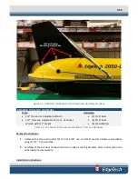
2050-DSS SIDE SCAN AND SUB-BOTTOM SYSTEM
0024048_REV_A
REQUIRED TOOLS AND HARDWARE
Tools:
•
9/16” Crescent or Adjustable Wrench
•
9/16” Crescent, Adjustable Wrench of Socket
Wrench with x” Socket
•
Cutting Plyers
Hardware:
•
[4] 3/8” Standard Flat
Washers
•
[4] 3/8” Hex Nuts
•
[2] Bottle Clamps
•
[2] Rubber Strips
Table 5-3: Sonar Processor Installation and Removal Tools and Hardware
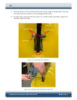
WARNING!
Power down the system and disconnect the cable from
Starmux IV. Injury or death can occur if the exposed connector on the tow
cable is energized. Always connect the tow cable to the tow vehicle first.
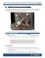
Sonar Processor Removal Instructions
1.
Power down the 2050-DSS system and disconnect the tow vehicle power and data cable.
2.
Remove tow vehicle’s upper-shell. See the
section of this manual
for detailed instructions.
3.
Note the installed roll position of the horizontally installed processor endcap and any cabling
configurations necessary for re-installation.
4.
Unplug all cabling from the processor end cap connectors or the connectors of the attached
electronics. Install dummy plugs into connectors where needed.
5.
Remove the [2] Bottle Clamps by removing the [2] rubber strips and unthreading the [4] nut and
washer assemblies using the 9/16” wrenches. The bolts cannot be removed.
6.
Carefully lift the electronics bottle from the tow vehicle.
Sonar Processor Installation Instructions
1.
Remove tow vehicle’s upper-shell. See the
section of this manual
for detailed instructions.
2.
Carefully set the electronics bottle back in place, positioning it in the roll position noted when
removing the sonar processor bottle.
3.
Install the [2] Bottle Clamps by replacing the [2] rubber strips and threading the [4] nut and washer
assemblies using the 9/16” wrenches.
4.
Plug in all cabling.
5.
Install the tow vehicle’s upper-shell
Содержание 2050-DSS
Страница 14: ...xiv 2050 DSS Side Scan and Sub Bottom System 0024048_REV_A A 0 KITS 6 66...
Страница 32: ...2 15 2 4 5 2050 DSS Side Scan Transducer Drawing Figure 2 5 2050 DSS Side Scan Array Drawing 0019213...
Страница 33: ...2 4 6 2050 DSS Test Cable Drawing Figure 2 6 Test Cable 0011690...
Страница 35: ...Figure 2 8 2050 DSS Rack Mounted Option...
Страница 38: ...3 21 3 1 2 2050 DSS Sonar Processor Diagram Figure 3 3 2050 DSS Sonar Processor Diagram 0023520...