


5-55
=
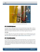
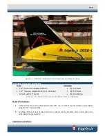
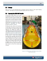
Figure 5-1: 2050-DSS Tail Rudder [3] Bolt Hardware Assembly Locations
REQUIRED TOOLS AND HARDWARE
Tools:
•
1/2” Crescent or Adjustable Wrench
•
1/2” Crescent, Adjustable Wrench of Socket
Wrench with 1/2” Socket
Hardware:
•
[3] 5/16” Bolts
•
[3] 5/16” Nuts
•
[6] 5/16 Washers
Table 5-1: Tail Rudder Removal and Installation Tools and Hardware
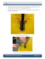
Removal Instructions:
1.
Unthread the three tail rudder 5/16” bolt, 5/16” nut, and 5/16” washer hardware assemblies
using [2] 1/2” inch wrenches.
2.
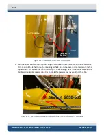
Carefully lift the tail clear of the vehicle’s [3] rudder mounting brackets. Store rudder and retain
all hardware for reassembly.
Installation Instructions:
[3] Tail Rudder
Mounting Assemblies
Содержание 2050-DSS
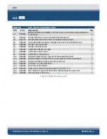
Страница 14: ...xiv 2050 DSS Side Scan and Sub Bottom System 0024048_REV_A A 0 KITS 6 66...
Страница 32: ...2 15 2 4 5 2050 DSS Side Scan Transducer Drawing Figure 2 5 2050 DSS Side Scan Array Drawing 0019213...
Страница 33: ...2 4 6 2050 DSS Test Cable Drawing Figure 2 6 Test Cable 0011690...
Страница 35: ...Figure 2 8 2050 DSS Rack Mounted Option...
Страница 38: ...3 21 3 1 2 2050 DSS Sonar Processor Diagram Figure 3 3 2050 DSS Sonar Processor Diagram 0023520...