


3-25
3.1.6
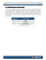
2050-DSS Responder I/O Interface (J8)
The 2050 has an interface for an external beacon/responder. The bulkhead is wired to the 2050 bottles
external sync, which is input from the topside “SYNC” BNC connector. The standard latency for the trigger
to pass through the system from topside to output from the tow fish is approximately 4ms. The wiring
for the bulkhead is listed in the table below. EdgeTech has options for different cables available for
interfacing to various devices. This connector also can be configured using software to be used as an
external trigger input or output to sync the sonar system with other devices. Contact
S
ERVICE
for details.
CONNECTOR J8
(MCBH5F)
DEFAULT WIRING
1
+27VDC
2
0 VDC
3
TRIGGER GND
4
TRIGGER A IN/OUT
5
FSK TRIGGER OUT (Responder)
Table 3-3: Responder IO Pin Outs
Содержание 2050-DSS
Страница 14: ...xiv 2050 DSS Side Scan and Sub Bottom System 0024048_REV_A A 0 KITS 6 66...
Страница 32: ...2 15 2 4 5 2050 DSS Side Scan Transducer Drawing Figure 2 5 2050 DSS Side Scan Array Drawing 0019213...
Страница 33: ...2 4 6 2050 DSS Test Cable Drawing Figure 2 6 Test Cable 0011690...
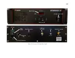
Страница 35: ...Figure 2 8 2050 DSS Rack Mounted Option...
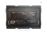
Страница 38: ...3 21 3 1 2 2050 DSS Sonar Processor Diagram Figure 3 3 2050 DSS Sonar Processor Diagram 0023520...