6.0: TROUBLESHOOTING
6-2
2000-DSS COMBINED SONAR
0009335_REV_D
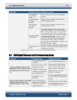
SYMPTOM
PROBABLE CAUSE CORRECTIVE ACTION
LAN settings are
not properly
setup.
for TCP/IP address
settings.
Modem settings
incorrect.
Check modem settings per subsection
Modem
disconnected
internally on
topside.
Check modem settings per subsection
Improper settings
in DISCOVER.
In
DISCOVER 2000-C Dual Frequency Side
Scan
, choose Network from the Configuration
menu and verify that the Sonar IP Address is
127.0.0.1 and the Sonar Port Number is 1602.
In
DISCOVER Sub-Bottom
, choose Control
Panel from the Sonar menu and select the
Network tab from the Options dialog box.
Verify that the TCP/IP Address is 127.0.0.1 and
the TCP/IP Socket is 1600.
The tow vehicle is
faulty.
Verify tow vehicle on a different 2000 Topside
Processor. Verify 2000 Topside Processor with
a different tow vehicle.
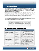
Table 6-1: 2000 Digital Telemetry Link Troubleshooting Guide
6.2
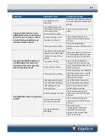
2000 Digital Telemetry Link Troubleshooting Guide
SYMPTOM
PROBABLE CAUSE
CORRECTIVE ACTION
The green POWER indicator on the
2000 Digital Telemetry Link does not
illuminate when the unit is turned
on.
The POWER switch is not
turned on.
Verify the POWER switch is on.
No AC power. When using
AC power connector.
Verify that the 2000 Topside
Processor is connected to AC
power. Check the AC power.
5-amp fuses on rear panel
of 2000 Topside Processor
AC connection bad.
Check fuses for continuity.
Replace if necessary.
The indicator is not
operating.
Open the 2000 Digital Telemetry
Link and check the indicator and
wiring.
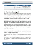
The green LAN indicator on the 2000
Digital Telemetry Link does not
illuminate when the unit is turned
on.
There is no connection
between the 2000 Digital
Telemetry Link and the
Topside Processor.
Check LAN connections between
the 2000 Digital Telemetry Link
and the Topside Processor.
Содержание 2000-DSS
Страница 20: ......
Страница 56: ...Figure 4 2 2000 Digital Telemetry Link Electronics Block Diagram...
Страница 57: ...Figure 4 3 2000 Digital Telemetry Link Wiring Diagram...
Страница 59: ...Figure 4 4 Tow Vehicle Electronic Block Diagram...
Страница 60: ...Figure 4 5 Tow Vehicle Interconnect Drawing...
Страница 63: ...Figure 4 6 Armored Cable PMI Grip Unterminated Topside...
Страница 64: ...Figure 4 7 Test Cable...
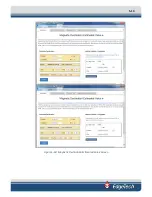
Страница 77: ...5 13 Figure 5 16 Magnetic Declination Estimated Value Screen...
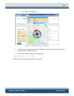
Страница 79: ...5 15 getDeclination CR Figure 5 18...
Страница 80: ......
Страница 94: ......
Страница 96: ......
Страница 98: ......

