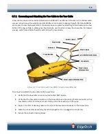

3-11
3.8
System Activation and Test
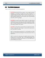
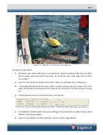
After the connections to the 2000 Topside Processor and the 2000 Digital Telemetry Link have been
completed, the 2000 Series Combined Side Scan Sonar and Sub-Bottom Profiling System can be activated
and some pre-deployment checks performed prior to deployment of the tow vehicle as a test to verify
that the system is operating properly.
When performing the system activation and test, refer to sub-section
for the location and description of the controls and indicators. In
addition, should the system not activate properly or the pre-deployment checks fail, refer to section
for assistance on how to isolate and correct the problem.
NOTE:
The DISCOVER software requires license activation which is
performed either directly in the tow vehicle or by inserting a dongle into
an available USB port on the Topside Processor. If in the tow vehicle, no
action is required.
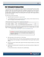
3.8.1
Activating the System
To activate the system:
1.
Turn on the LCD monitors.
2.
Turn on the POWER switch on the back panel of the Topside Processor. This switch can be left in
the on position at all times if desired.
3.
Turn on the SYSTEM POWER switch on the front panel.
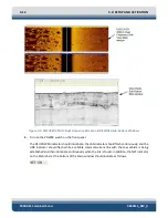
The SYSTEM POWER indicator should illuminate, and the HDD indicator should flash while the
Windows desktop opens. Then the EdgeTech DISCOVER 2000-C Dual Frequency Side Scan and
DISCOVER Sub Bottom software open to the Main windows as shown in
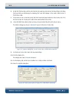
4.
Turn on the LINE switch on the back panel of the 2000 Digital Telemetry Link. This switch can be
left in the on position at all times if desired.
Содержание 2000-DSS
Страница 20: ......
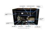
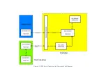
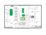
Страница 56: ...Figure 4 2 2000 Digital Telemetry Link Electronics Block Diagram...
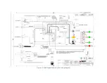
Страница 57: ...Figure 4 3 2000 Digital Telemetry Link Wiring Diagram...
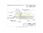
Страница 59: ...Figure 4 4 Tow Vehicle Electronic Block Diagram...
Страница 60: ...Figure 4 5 Tow Vehicle Interconnect Drawing...
Страница 63: ...Figure 4 6 Armored Cable PMI Grip Unterminated Topside...
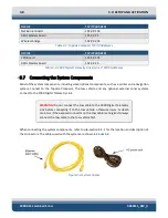
Страница 64: ...Figure 4 7 Test Cable...
Страница 77: ...5 13 Figure 5 16 Magnetic Declination Estimated Value Screen...
Страница 79: ...5 15 getDeclination CR Figure 5 18...
Страница 80: ......
Страница 94: ......
Страница 96: ......
Страница 98: ......


