


1-7
sediment layering and display of along track and across track imagery, reduction of side lobes for minimal
reception of undesired echoes, additional processing gain for energy efficiency, and a Gaussian shaped
amplitude spectrum of the outgoing pulse to preserve resolution and bandwidth with attenuation.
1.4.1
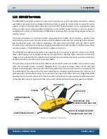
Separate Sub-Bottom Acoustic Projectors and Receivers
The side scan sonar uses a line array of piezoelectric elements to both transmit and receive the acoustic
signals, one on the port side of the tow vehicle and one on the starboard side. The sub-bottom sonar uses
separate acoustic projectors and receivers. The projectors are wide band piston type transducers, and the
receivers are hydrophone arrays composed of lead piezoelectric
zirconate titanate
(PZT) crystals. The
transducers are mounted in the forward section of the tow vehicle, and the hydrophone arrays are
mounted aft. The use of separate transmitting transducers and receiving hydrophone arrays preserves
linearity and allows the simultaneous transmission and reception of the acoustic signals. The transducers
and hydrophone arrays are mounted beneath acoustic baffles which minimize direct path, tow vehicle
and surface reflections.
1.4.2
High Signal-to-Noise Ratio
Full Spectrum Chirp technology does not use a conventional matched filter, the correlation filter that is
widely used to compress FM signals, to process wide band signals. Rather it uses proprietary amplitude
and phase weighting functions for the transmitted pulse and a pulse compression filter that maximizes
the SNR of the acoustic images over a wide band of operating frequencies. These functions provide a
significant SNR improvement in the imagery over other pulse and chirp side scan and sub-bottom sonars
with band limited components that are limited in dynamic range.
1.4.3
High Repeatability
The frequency range of operation is determined by the acoustic characteristics of the transmitter and
receiver mounted in the towed vehicle. For the side scan sonar, the transmit frequency is selected based
on the desired range and resolution required. For sub-bottom profiling, the frequency is selected based
on the sub-bottom conditions at the survey site and the type of sub-bottom features that need to be
imaged. The FM pulses are generated by a D/A converter with a wide dynamic range and a transmitter
with linear components. Therefore, the energy, amplitude and phase characteristics of the acoustic pulses
can be precisely controlled. This precision produces high repeatability and signal definition.
1.4.4
High Resolution
Normally, when using long pulses, resolution is reduced. However, after correlation processing the
received signals, a very sharp wavelet is produced that has a duration equal to the inverse of the sweep
bandwidth. Therefore, the more bandwidth that is used, the sharper this pulse will become. Side scan and
sub-bottom signals received at the surface pass through a software controlled programmable gain
amplifier before being digitized with a 16-bit analog-to-digital (A/D) converter. The FM pulse is then
Содержание 2000-DSS
Страница 20: ......
Страница 56: ...Figure 4 2 2000 Digital Telemetry Link Electronics Block Diagram...
Страница 57: ...Figure 4 3 2000 Digital Telemetry Link Wiring Diagram...
Страница 59: ...Figure 4 4 Tow Vehicle Electronic Block Diagram...
Страница 60: ...Figure 4 5 Tow Vehicle Interconnect Drawing...
Страница 63: ...Figure 4 6 Armored Cable PMI Grip Unterminated Topside...
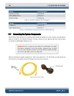
Страница 64: ...Figure 4 7 Test Cable...
Страница 77: ...5 13 Figure 5 16 Magnetic Declination Estimated Value Screen...
Страница 79: ...5 15 getDeclination CR Figure 5 18...
Страница 80: ......
Страница 94: ......
Страница 96: ......
Страница 98: ......


