Chapter 2 — Setting Up
15
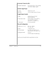
The four digital output connections of the Instrument Connection port
provide a means to control external devices. The digital output signals
can be configured as either TTL signal levels or contact closures, by
installing or removing a set of links,
. These digital
outputs can be used to signal external devices such as autosamplers,
fraction collectors, or autoinjectors. More detail on these controls is
provided on
.
The recording unit uses a universal input switching power supply.
Detector Inputs
Each of the PowerChrom unit’s analog input differential amplifiers have
independently computer-controlled gain from
×
1 (10 V range setting) to
×
5000 (2 mV range setting). Applying more than ±30 V to the detector
inputs could damage the circuitry.
Each input is fitted with a 900 Hz second order Bessel anti-aliasing low-
pass filter which eliminates high frequency interference. Input
impedance is 1 MΩ.
The operation of the input amplifiers is illustrated by the block diagram
in
Using differential analog inputs for the detectors gives the system
greater immunity to external electrical interference, when used in
conjunction with a suitable cable. The best type of detector cable would
be a twisted pair with a braided shield, as shown in
shield should be connected to the detector’s analog ground, or to the
COM pin of CH1 or CH2, but not to both.
Analog Output
The analog output provides a computer–controlled variable output (0 –
10 V, at up to 10 mA) that can be used to control peripheral devices.
The analog voltage output is accessed via the DAC pins in the
Instrument Connection port (DAC + and COM),
The voltage is controlled using the PowerChrom software Method
tables, see the
PowerChrom Software Manual
for more information.
Содержание PowerChrom 280
Страница 4: ...iv PowerChrom ...
Страница 26: ...22 PowerChrom ...
Страница 34: ...30 PowerChrom ...


