background image


417101634_Lubo-DryExx_Advanced 

- 25 - 

Rev. 07-01.15 


10.  Wartung 

10.1  Wartungshinweis 

Die Dosierstation wird im Herstellerwerk geprüft und befindet sich beim Versand in 

ordnungsgemäßem und sicherem technischen Zustand. 
Zur Sicherung dieses Zustands und der des störungsfreien Betriebs muss der Benutzer 

den Inhalt dieser Bedienungsanleitung aufmerksam lesen. 


VORSICHT 

Als wesentliche Voraussetzung ist zu sichern, dass das Gerät vor der Durchführung von 

Wartungs-  und Instandsetzungsarbeiten vom Netz getrennt wird und nicht unter Druck 

steht. Nach Teilewechsel ist eine Funktionsprüfung durchzuführen.


WARNUNG 

Wartungsarbeiten bei angeschlossenem Gerät dürfen nur von qualifizierten Personen 

durchgeführt werden. 
Bei Einsatz von gefährlichen Substanzen sind die entsprechenden 

Sicherheitsanweisungen zu beachten. Das Bedienpersonal muss mit geeigneter 

persönlicher Schutzausrüstung (Schutzbrille, Schutzhandschuhe, Schürze)  ausgestattet 

sein.


10.2  Wartungsarbeiten 

Bei der Durchführung von Wartungsarbeiten im System 

DryExx

®


ist besonders auf 

folgende Punkte zu achten: 

 Kontrolle auf Ablagerungen und Schmutzansammlungen  

 Anliegen der benötigten Dosierleistung 

 Funktion der Magnetventile 

 Kontrolle und ggf. Reinigung von Düsen und Filtern 

 Kontrolle der Saugleitung auf Funktion (Sieb und Ventil im Eintritt unten, 

Schutzkappe) 

 Saug- und Druckventile an der Pumpe  

 Funktionskontrolle des Rückführungsschlauchs vom Entlastungsventil. 

Der Schlauch muss freies Gefälle haben. 

 Kontrolle der Saug- und Druckleitungen auf leckfreien Anschluss 


Содержание Lubo-DryExx

Страница 1: ...x Advanced System f r die Dosierung von DryExx Bandschmierprodukten mit Steuerung DryExx Advanced f r bis zu 16 Schmierkreise in 10 Anlagen Application System for DryExx Conveyor Belt Lubrication Prod...

Страница 2: ...8 4 5 4 DryExx Advanced DP 8 4 5 5 DryExx Advanced ETH 8 4 5 6 DryExx Universal 9 4 5 7 DryExx Venture 9 5 Montage 10 6 Anschluss 11 6 1 Anschluss bersicht DryExx 11 6 2 Wandmontage DryExx 11 7 Steue...
Страница 3: ...hrt werden Die Benutzung der DryExx Dosierstationen muss entsprechend den Anweisungen in der technischen Beschreibung erfolgen Es d rfen nur Originalteile f r Instandsetzungs und Wartungsarbeiten verw...

Страница 4: ...r und Reinigungsprodukt DryExx sowie beim Auswechseln des Vorratsbeh lters m ssen die Sicherheitsvorschriften f r den Umgang mit Chemikalien eingehalten werden 2 4 Spezielle Sicherheitshinweise Die St...

Страница 5: ...yExx_Advanced 5 Rev 07 01 15 3 Lieferumfang Abb 3 1 Dosierstation Lubo DryExx Art Nr 182830 Art Nr 182831 Abb 3 2 Steuerung DryExx Advanced Art Nr 182837 Abb 3 3 Betriebsanleitung Lubo DryExx Advanced...

Страница 6: ...0 mit Panel TP177B im Edelstahlgeh use und steuert alle f r den Prozess notwendigen Zeiten Taktungen Abl ufe und Meldungen in DryExx Systemen mit bis zu 16 Schmierkreisen in maximal 10 Anlagen Die Ste...

Страница 7: ...druck schaltet die Pumpe selbstt tig ab 4 4 Aufbau Dosierstation DryExx ber eine Sauglanze mit Leermeldesignal f rdert eine Druckluftmembranpumpe das Bandschmiermittel zu den Schmierkreisen mit den D...

Страница 8: ...z hler angeschlossen werden Die Verbrauchsmenge kann optional ber einen Durchflussmesser erfasst und ebenfalls am TP abgerufen werden 4 5 4 DryExx Advanced DP Basis hierf r ist eine Siemens S7 300 mit...

Страница 9: ...twendigen Zeiten Taktungen Abl ufe und Meldungen in DryExx Systemen mit bis zu 48 Schmier und Reinigungskreisen an 3 Dosierstationen bei vollst ndigem Ausbau Die Steuerung DryExx Universal arbeitet au...

Страница 10: ...ryExx Dosierstationen werden im Herstellerwerk vormontiert und sind bei Lieferung anschlussfertig und zur Wandmontage vorbereitet Die Dosierstationen sind ausschlie lich mit einer DryExx Steuerung zu...

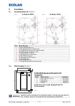
Страница 11: ...Druckluftanschluss Dosierpumpe 9 Druckluftfilterregler 10 Druckluftanschluss 8 6 11 3 2 Wege Magnetventil Steuerventil Pumpe 6 2 Wandmontage DryExx 30 25 360 Lubo DryExx 410 550 Zur Wandbefestigung si...

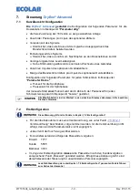
Страница 12: ...Pulszeit f r die Spr hphase Pausenzeit f r der Spr hphase der manuelle Start einer Pulszeit wird durch Abbruch der Pausenzeit f r jeden Schmierkreis separat im Men punkt booster gestartet HINWEIS Alle...

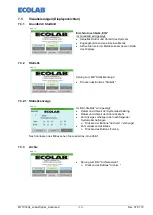
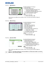
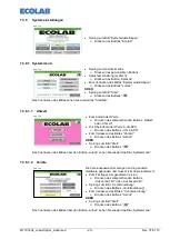
Страница 13: ...2 Statistik Abb 7 2 Sprung zum Bild Statistikanzeige Dr cken des Buttons Statistik 7 3 2 1 Statistikanzeige Abb 7 3 Im Bild Statistik wird gezeigt Datum und Uhrzeit der Systemabschaltung Datum und Uhr...

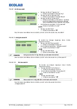
Страница 14: ...gen angezeigt denen Ventile zugeordnet wurden Sprung zum Bild Kreisauswahl Dr cken des Buttons Anlage xx Zum Verlassen des Bildes Anlagenauswahl Dr cken des Buttons zur ck ODER Sprung zum Bild Start D...

Страница 15: ...n des Buttons Param Kreise 7 3 4 1 Anlagenauswahl Abb 7 10 Es werden nur Anlagen angezeigt denen Ventile zugeordnet wurden Sprung zum Bild Kreisauswahl Dr cken des Buttons Anlage xx Zum Verlassen des...

Страница 16: ...des Bildes Dr cken des Buttons zur ck ODER Sprung zum Bild Start Dr cken des Buttons Nach Verlassen des Bildes ber den Button Zur ck sehen Sie wieder die Parameter Kreisauswahl 7 3 4 1 1 2 Parameterei...

Страница 17: ...elaufen ist wird das Signal aktiv Takt und Pausenzeit Soll Diese Zeiten werden benutzt wenn 1 Die Wartezeit Nach abgelaufen ist 2 Das Freigabesignal aktiv ist 3 Die Aktivzeit F r noch nicht abgelaufen...

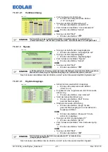
Страница 18: ...des Buttons Param allg Nach Verlassen des Bildes sehen Sie wieder das Hauptmen 7 3 7 1 Anzeige Parameter allgemein Abb 7 19 Das Bild enth lt folgende Anzeigen Zeit Entlastung Pumpe Zeit Vorspannen Sy...

Страница 19: ...g positiv Dosierabweichung negativ Dosierwert positiv Dosierwert negativ Zu den anderen Ventilen Dosierkreise Dr cken der Taste Dr cken der Taste Zum Festlegen des Soll Dosierwertes Dr cken des Button...

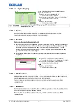
Страница 20: ...rzeit Zur bernahme der Werte in die SPS Dr cken des Buttons Uhr in SPS Zum Verlassen des Bildes Uhrzeit Dr cken des Buttons zur ck ODER Sprung zum Bild Start Dr cken des Buttons Nach Verlassen des Bil...

Страница 21: ...rt sind nicht alle Button zu sehen Manuelle Ansteuerung der Digitalen Ausg nge nur im Betriebszustand manuell Nach Verlassen des Bildes ber den Button zur ck sehen Sie wieder das Bild Systemmen 7 3 8...

Страница 22: ...Die Eingabe muss mit dem Bet tigen der Taste ENTER best tigt werden Ist dies erfolgt springen sie automatisch zur ck in das vorherige Bild und sie m ssen den gew nschten Button erneut bet tigen Bei E...

Страница 23: ...zu achten dass der Schlauch ohne Knicke und mit freiem Gef lle zum Liefergebinde verlegt wird 8 3 Bef llen des Verteilerleitungssystems Einregeln des Druckluftfilterreglers f r die Steuerluft der Pum...

Страница 24: ...d aus Sauglanze l 1125 mm 12 21 Zubeh r nicht im Lieferumfang 288460 Schutzh lse f r Sauglanze Zubeh r nicht im Lieferumfang 286191 Gewebeschlauch 12 21 PVC Zubeh r nicht im Lieferumfang 417400127 Typ...

Страница 25: ...on qualifizierten Personen durchgef hrt werden Bei Einsatz von gef hrlichen Substanzen sind die entsprechenden Sicherheitsanweisungen zu beachten Das Bedienpersonal muss mit geeigneter pers nlicher Sc...

Страница 26: ...symptom Ursache St rung Behebung Dosierpumpe saugt nicht an Siehe Pumpenhandbuch Siehe Pumpenhandbuch Verminderte Dosierleistung Luftsteuerleitung bringt zu wenig Druck Filterdruckregler und 3 2 Wege...

Страница 27: ...elstahl 12 2 Lubo DryExx Steuerung DryExx Advanced Spannungsversorgung 120 500 V 50 60 Hz Steuerspannung max 24 V DC Leistungsaufnahme max 2kVA Vorsicherung max 10 A Steuerungsmodul Siemens S7 313C An...

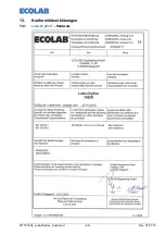
Страница 28: ...417101634_Lubo DryExx_Advanced 28 Rev 07 01 15 13 Konformit tserkl rungen 13 1 Lubo DryExx Hardware...

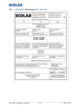
Страница 29: ...417101634_Lubo DryExx_Advanced 29 Rev 07 01 15 13 2 Lubo DryExx Steuerung DryExx Advanced Control Cabinet Art Nr 182837...

Страница 30: ...d 36 4 5 4 DryExx Advanced DP 36 4 5 5 DryExx Advanced ETH 36 4 5 6 DryExx Universal 36 4 5 7 DryExx Venture 37 5 Assembly 38 6 Connection 39 6 1 Connection Overview DryExx 39 6 2 Wall Mounting DryExx...

Страница 31: ...pair must be carried out by qualified and authorised specialists Use of the DryExx metering stations must be carried out in accordance with the instructions in the technical description Only genuine s...

Страница 32: ...eyor belt lubrication and cleaning material or when changing the hopper reservoir safety regulations for the handling of chemical substances must be observed 2 4 Special Safety Instructions The DryExx...

Страница 33: ...anced 33 Rev 07 01 15 3 Scope of supply fig 3 1 Metering station Lubo DryExx Art no 182830 Art no 182831 fig 3 2 Control System DryExx Advanced Art no 182837 fig 3 3 Operating Instruction Lubo DryExx...

Страница 34: ...e control system is based on a Siemens PLC S7 300 with a TP170B panel in stainless steel housing and controls all required times cycles procedures and reports in DryExx Systems with up to 16 lubricati...

Страница 35: ...tomatically 4 4 Configuration DryExx A diaphragm compressed air pump supplies the conveyor belt lubricant via a suction lance with an empty detector unit to the lubrication circuit with the nozzle fit...

Страница 36: ...g DryExx systems with up to 16 lubrication circuits in a maximum of 10 installations can be connected The lubrication circuits in the installations can be individually controlled A record of hours run...

Страница 37: ...ure Is tailor made to suit individual systems and is for DryExx systems with special requirements such as other control unit variants several metering stations for large installation complexes etc For...

Страница 38: ...mbly The DryExx metering stations are pre assembled by the manufacturer and are ready for connection and wall mounting on delivery The metering stations are only to be used with a DryExx control unit...

Страница 39: ...connection applicator pump 9 Compressed air filter regulator 10 Compressed air connection 8 6 11 3 2 Way Solenoid valve control valve pump 6 2 Wall Mounting DryExx 30 25 360 Lubo DryExx 410 550 For wa...

Страница 40: ...raying Pause time for spraying Manual start of one impulse time by means of interrupting the pause time for each lubricating circuit NOTE All options are displayed in plain text on the various screens...

Страница 41: ...line at the top of the screen 7 3 2 Statistics fig 7 2 To go to the Statistics screen Press Stat ON OFF 7 3 2 1 Statistics screens fig 7 3 The Statistics screen displays the following information Dat...

Страница 42: ...alves are allocated To go to the Circuit Selection screen Press System xx To leave the System Selection screen Press Back OR To go to the Start screen Press NOTE The selection screens for the daily mo...

Страница 43: ...t Parameters fig 7 9 To go to the Circuit Parameters screen Press Circuit Parameters 7 3 4 1 Area selection fig 7 10 The screen only displays Area if the valves are allocated To go to the Area Selecti...

Страница 44: ...ster Times Leave the picture Press Button Return OR To go to the Start screen Press After leaving the picture with button Return you see again the Parameter circuit selection 7 3 4 1 1 2 Parameter dis...

Страница 45: ...and break time will be used Actual status Activation This signal will be active if the time After is running down Pulse and break time default This times are used if 1 The waiting time After is down...

Страница 46: ...eral Parameters fig 7 18 To go to the General Parameters Press Para Generaly 7 3 7 1 Displays of Parameter Generaly fig 7 19 The display contains the following announcements Time relief pump Time pre...

Страница 47: ...tering value Metering deviation positive Metering deviation negative Metering value positive Metering value negative To the other valves metering circuits Press Button Press Button To configure the de...

Страница 48: ...7 25 To change values Press Date or Time To take a value into PLC Press time to PLC To leave Time Press Back OR To go to the Start screen Press After leaving the picture with button Return you see ag...

Страница 49: ...sion and the current mode of operation not all buttons are shown Manual control of the digital outputs only in the operating condition manually After leaving the picture with button Back you see again...

Страница 50: ...e input of the password effected The input must be confirmed with the pressing of the key ENTER If this took place they jump automatically back into the previous picture and they must again operate th...

Страница 51: ...and that it is routed back to the hopper reservoir with a free downwards gradient 8 3 Filling the supply system Set the compressed air filter regulator for the controlling air pressure for the pump t...

Страница 52: ...lance l 1125 mm 12 21 Accessories not scope of supply 288460 Suction lance protective cover Accessories not scope of supply 286191 Fabric hose 12 21 PVC Accessories not scope of supply 417400127 Type...

Страница 53: ...s been connected up should only be carried out by qualified personnel When using hazardous substances the appropriate safety instructions are to be observed Operators must be equipped with their own p...

Страница 54: ...ause Fault Remedy No suction at applicator pump See pump handbook See pump handbook Reduced applicator performance Air control circuit produces to little pressure Check filter pressure regulator and 3...

Страница 55: ...l Console Cover Stainless steel 12 2 Lubo DryExx Control System DryExx Advanced Power supply 120 500 V 50 60 Hz Control voltage max 24 V DC Received power max 2kVA Back up fuse max 10 A Control module...

Страница 56: ...417101634_Lubo DryExx_Advanced 56 Rev 07 01 15 13 Declarations of conformity 13 1 Lubo DryExx Hardware...

Страница 57: ...417101634_Lubo DryExx_Advanced 57 Rev 07 01 15 13 2 Lubo DryExx Control System DryExx Advanced Control Cabinet Art no 182837...

Страница 58: ...of issue 03 04 2012 Letzte nderung last changing 22 01 2015 Copyright Ecolab Engineering GmbH 2014 Alle Rechte vorbehalten All rights reserved Nachdruck auch auszugsweise nur mit Genehmigung der Firm...

Отзывы: